Product Description
1.Product Description
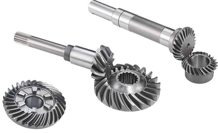
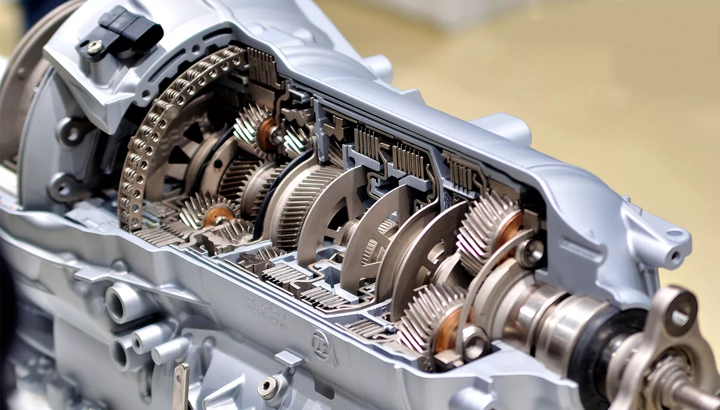
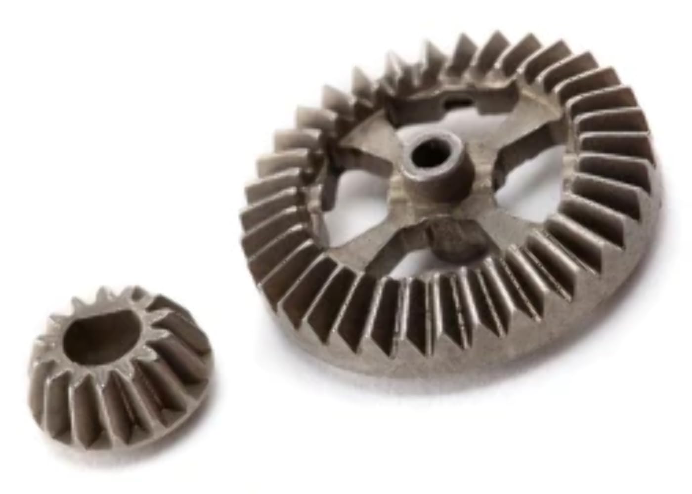
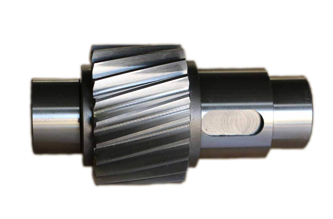
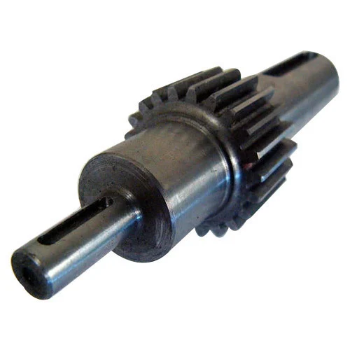
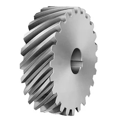
This Gear shaft, Herringbone Gear Shaft, Bevel Gear, Eccentric Shaft mainly used on vessel engine, fan internal gear
2.1. Gear Shaft Processing
Gear Shaft drawing CHECK, Make Forging Mold, Forging Mold Quality Inspection Check, Machine Processing, Check Size\Hardness\Surface Finish and other technical parameters on drawing.
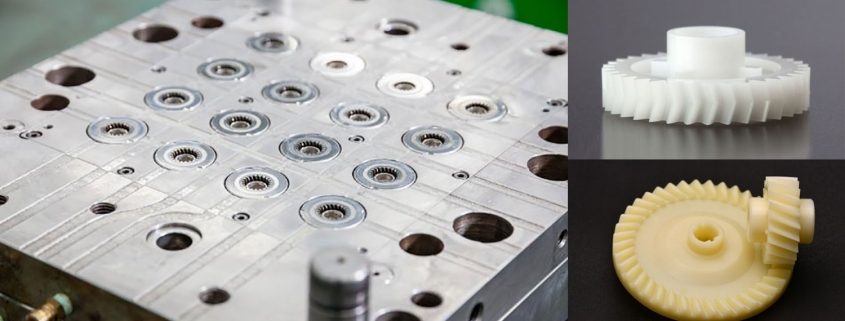
2.2. Herringbone Gear Shaft Package
Spray anti-rust oil on Herringbone Gear Shaft, Wrap waterproof cloth around Gear Shaft for reducer, Prepare package by shaft shape&weight to choose steel frame, steel support or wooden box etc.
2.3. OEM Customized Gear Shaft
We supply OEM SERVICE, customized herringbone gear shaft with big module, more than 1tons big weight, more than 3m length, 42CrMo/35CrMo or your specified required material gear shaft.
2.Product Technical info.
| Module | m | Range: 5~70 |
| Gear Teeth Number | z | OEM by drawing’s technical parameters |
| Teeth Height | H | OEM by drawing’s technical parameters |
| Teeth Thickness | S | OEM by drawing’s technical parameters |
| Tooth pitch | P | OEM by drawing’s technical parameters |
| Tooth addendum | Ha | OEM by drawing’s technical parameters |
| Tooth dedendum | Hf | OEM by drawing’s technical parameters |
| Working height | h’ | OEM by drawing’s technical parameters |
| Bottom clearance | C | OEM by drawing’s technical parameters |
| Pressure Angle | α | OEM by drawing’s technical parameters |
| Helix Angle, | OEM by drawing’s technical parameters | |
| Surface hardness | HRC | Range: HRC 50~HRC63(Quenching) |
| Hardness: | HB | Range: HB150~HB280; Hardening Tempering/ Hardened Tooth Surface |
| Surface finish | Range: Ra1.6~Ra3.2 | |
| Tooth surface roughness | Ra | Range: ≥0.4 |
| Gear Accuracy Grade | Grade Range: 5-6-7-8-9 (ISO 1328) | |
| Diameter | D | Range: 1m~16m |
| Weight | Kg | Range: Min. 100kg~Max. 80tons Single Piece |
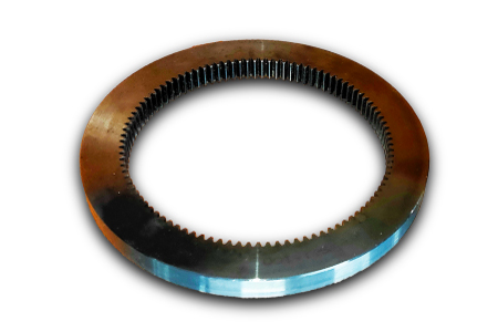
| Gear Position | Internal/External Gear | |
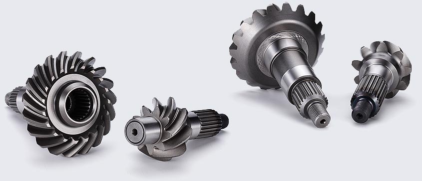
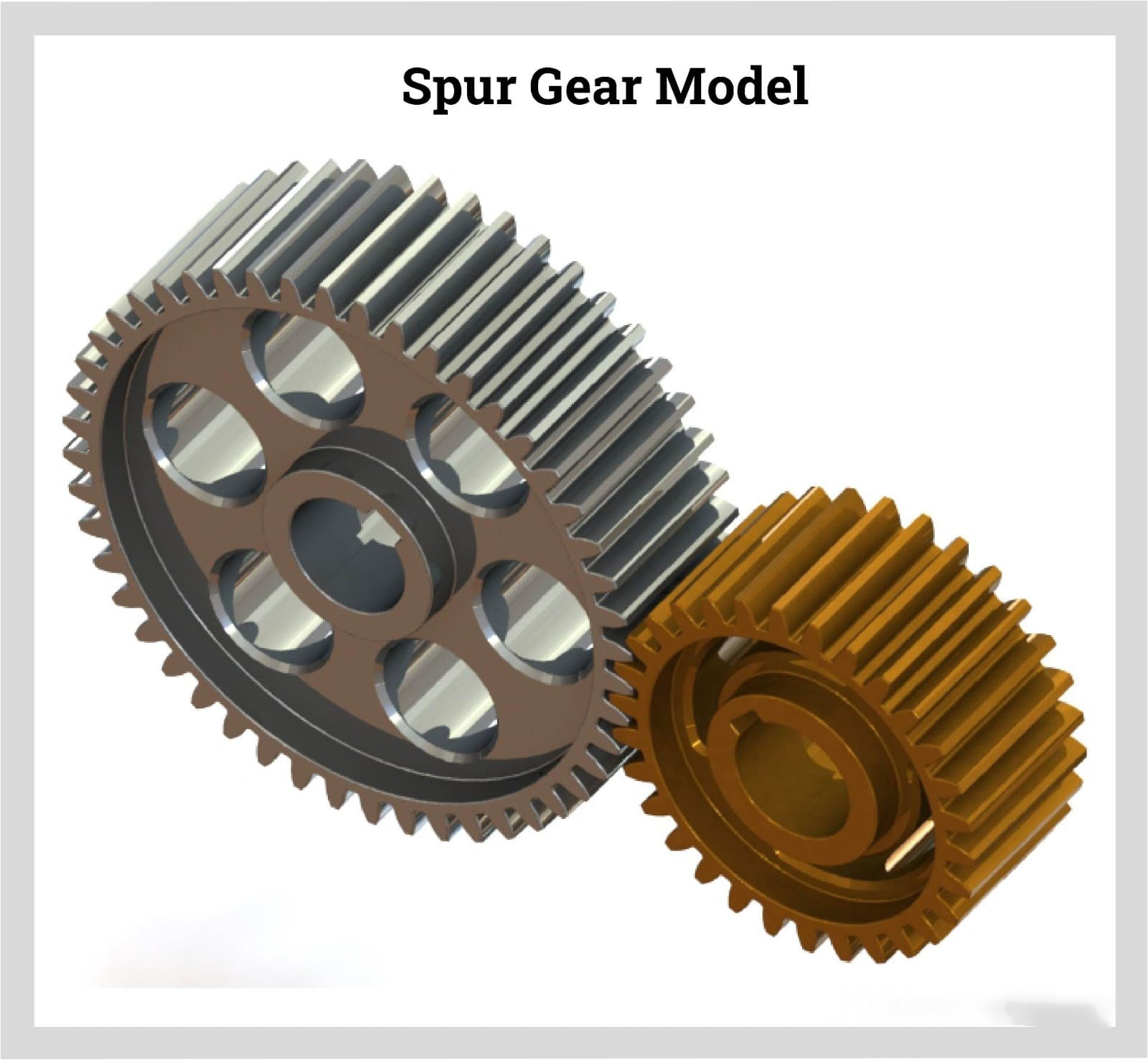
| Toothed Portion Shape | Spur Gear/Bevel/Spiral/Helical/Straight | |
| Shaft shape | Herringbone Gear Shaft / Gear Shaft / Eccentric Shaft / Spur Gear / Girth Gear / Gear Wheel | |
| Material | Forging/ Casting |
Forging/ Casting 45/42CrMo/40Cr or OEM |
| Manufacturing Method | Cut Gear | |
| Gear Teeth Milling | √ | |
| Gear Teeth Grinding | √ | |
| Heat Treatment | Quenching /Carburizing | |
| Sand Blasting | Null | |
| Testing | UT\MT | |
| Trademark | TOTEM/OEM | |
| Application | Gearbox, Reducer, Petroleum,Cement,Mining,Metallurgy etc. Wind driven generator,vertical mill reducer,oil rig helical gear,petroleum slurry pump gear shaft |
|
| Transport Package | Export package (wooden box, steel frame etc.) | |
| Origin | China | |
| HS Code | 8483409000 |
Material Comparison List
| STEEL CODE GRADES COMPARISON | |||||
| CHINA/GB | ISO | ГΟСТ | ASTM | JIS | DIN |
| 45 | C45E4 | 45 | 1045 | S45C | CK45 |
| 40Cr | 41Cr4 | 40X | 5140 | SCr440 | 41Cr4 |
| 20CrMo | 18CrMo4 | 20ХМ | 4118 | SCM22 | 25CrMo4 |
| 42CrMo | 42CrMo4 | 38XM | 4140 | SCM440 | 42CrMo4 |
| 20CrMnTi | 18XГT | SMK22 | |||
| 20Cr2Ni4 | 20X2H4A | ||||
| 20CrNiMo | 20CrNiMo2 | 20XHM | 8720 | SNCM220 | 21NiCrMo2 |
| 40CrNiMoA | 40XH2MA/ 40XHMA |
4340 | SNCM439 | 40NiCrMo6/ 36NiCrMo4 |
|
| 20CrNi2Mo | 20NiCrMo7 | 20XH2MA | 4320 | SNCM420 | |
3.Totem Service
CHINAMFG Machinery focus on supplying GEAR SHAFT, ECCENTRIC SHAFT, HERRINGBONE GEAR, BEVEL GEAR, INTERNAL GEAR and other parts for transmission devices & equipments(large industrial reducers & drivers). Which were mainly used in the fields of port facilities, cement, mining, metallurgical industry etc. We invested in several machine processing factories,forging factories and casting factories,relies on these strong reliable and high-quality supplier network, to let our customers worry free.
TOTEM Philosophy: Quality-No.1, Integrity- No.1, Service- No.1
24hrs Salesman on-line, guarantee quick and positive feedback. Experienced and Professional Forwarder Guarantee Log. transportation.
4.About TOTEM
1. Workshop & Processing Strength
2. Testing Facilities
3. Customer Inspection & Shipping
5. Contact Us
ZheJiang CHINAMFG Machinery Co.,Ltd
Facebook: ZheJiang Totem
/* January 22, 2571 19:08:37 */!function(){function s(e,r){var a,o={};try{e&&e.split(“,”).forEach(function(e,t){e&&(a=e.match(/(.*?):(.*)$/))&&1
| Application: | Motor, Motorcycle, Machinery, Marine, Cement |
|---|---|
| Hardness: | Hardened Tooth Surface |
| Gear Position: | Internal/External |
| Manufacturing Method: | Cast Gear |
| Toothed Portion Shape: | Bevel Wheel |
| Material: | Cast Steel |
| Customization: |
Available
| Customized Request |
|---|

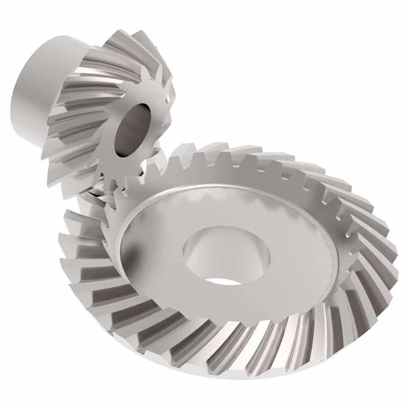
What are the advantages and disadvantages of using a bevel gear?
Bevel gears offer several advantages and disadvantages when used in mechanical systems. Understanding these pros and cons is crucial for selecting the appropriate gear type for a given application. Here’s a detailed explanation of the advantages and disadvantages of using a bevel gear:
Advantages of Bevel Gears:
- Power Transmission at Different Angles: Bevel gears are specifically designed to transmit power between intersecting shafts at different angles. They allow for efficient torque transmission and direction changes in applications where the input and output shafts are not parallel. This flexibility makes bevel gears suitable for a wide range of mechanical systems.
- Compact Design: Bevel gears have a compact and space-efficient design, allowing them to be used in applications with limited space constraints. Their ability to transmit power at an angle helps in optimizing the layout and arrangement of components in machinery and equipment.
- High Efficiency: Well-designed and properly maintained bevel gears can achieve high power transmission efficiency, typically above 95%. The efficient tooth engagement and load distribution in bevel gears minimize power losses due to friction and mechanical inefficiencies, resulting in energy-efficient operation.
- Smooth and Quiet Operation: Bevel gears generally provide smooth and quiet operation in properly designed and well-maintained systems. The meshing of the gear teeth is designed to minimize noise and vibration, ensuring smooth power transmission and reducing the need for additional noise-reducing measures.
- Versatility: Bevel gears are available in various configurations, including straight bevel, spiral bevel, and hypoid bevel gears. This versatility allows them to be used in a wide range of applications across different industries, accommodating different load capacities, speed requirements, and operating conditions.
- High Load Capacity: Bevel gears are capable of handling high loads and transmitting substantial amounts of torque. Their robust design, accurate tooth engagement, and strong materials make them suitable for heavy-duty applications where reliable power transmission is required.
Disadvantages of Bevel Gears:
- Complex Manufacturing: Bevel gears are more complex to manufacture compared to other gear types due to their three-dimensional shape and intricate tooth profiles. The manufacturing process involves specialized equipment and expertise, which can increase production costs.
- Cost: Bevel gears, especially those with high precision and load capacities, can be relatively expensive compared to other types of gears. The cost of materials, manufacturing complexity, and quality requirements contribute to their higher price.
- Potential for Noise and Vibration: In certain operating conditions, such as high speeds or misaligned gears, bevel gears can generate noise and vibration. This can be mitigated through proper design, accurate manufacturing, and maintenance practices, but additional measures may be necessary to reduce noise and vibration levels in some applications.
- Sensitive to Misalignment: Bevel gears are sensitive to misalignment, which can lead to increased friction, accelerated wear, and reduced efficiency. Proper alignment and control of backlash are essential for optimal performance and longevity of the gear system.
- Complex Lubrication: The lubrication of bevel gears can be more challenging compared to parallel-axis gears. Due to their angled tooth engagement, ensuring proper lubrication film thickness and distribution across the gear teeth requires careful consideration. Inadequate or improper lubrication can result in increased friction, wear, and reduced efficiency.
It’s important to consider these advantages and disadvantages of bevel gears in the context of specific applications and operating conditions. Proper design, selection, manufacturing, and maintenance practices can help maximize the benefits of bevel gears while mitigating their limitations.

Can bevel gears be used in heavy-duty machinery and equipment?
Yes, bevel gears can be used in heavy-duty machinery and equipment due to their ability to transmit high torque, handle heavy loads, and operate in various orientations. Here’s a detailed explanation:
Bevel gears are versatile and robust, making them suitable for heavy-duty applications in machinery and equipment. Here are several reasons why bevel gears are commonly used in heavy-duty applications:
- High Torque Transmission: Bevel gears are capable of transmitting high torque between intersecting shafts. They have a large contact area, which allows for efficient power transmission without compromising strength. This makes them well-suited for heavy-duty machinery that requires high torque output.
- Heavy Load Handling: Bevel gears are designed to withstand heavy loads, including radial loads, axial loads, and bending moments. Their sturdy construction and tooth geometry enable them to distribute the load evenly across the gear teeth, minimizing localized stress and preventing premature failure. This load-handling capability makes bevel gears ideal for heavy-duty applications that involve substantial forces and loads.
- Various Orientations: Bevel gears can be used in different orientations, including horizontal, vertical, and angled arrangements. This versatility allows them to adapt to the specific requirements of heavy-duty machinery and equipment, regardless of the shaft orientation. Whether it’s a gearbox, power transmission system, or lifting equipment, bevel gears can be designed and installed to accommodate the desired orientation.
- Durable Construction: Bevel gears are typically manufactured using high-strength materials, such as alloy steels or case-hardened steels, to ensure durability and resistance to wear. They undergo precise machining, grinding, and heat treatment processes to achieve the required hardness, surface finish, and dimensional accuracy. The robust construction and quality manufacturing of bevel gears make them capable of withstanding the demanding conditions of heavy-duty applications.
- Application-Specific Designs: Bevel gears can be customized and optimized for specific heavy-duty applications. Gear designers can tailor the gear parameters, such as tooth profile, size, and material selection, to match the requirements of the machinery or equipment. This flexibility in design allows for the creation of bevel gears that are specifically engineered to handle the unique demands of heavy-duty applications.
Overall, bevel gears are well-suited for heavy-duty machinery and equipment due to their high torque transmission capability, load-handling capacity, adaptability to various orientations, durable construction, and customizable designs. By selecting the appropriate bevel gear types, sizes, and materials, engineers can ensure reliable and efficient operation in heavy-duty applications across industries such as construction, mining, agriculture, and transportation.
It is important to note that the specific design requirements and load conditions of each heavy-duty application should be carefully considered during the gear selection and design process. Consulting with experienced engineers and adhering to industry standards will help ensure that the chosen bevel gears are suitable for the intended heavy-duty machinery or equipment.

Are there different types of bevel gears available?
Yes, there are different types of bevel gears available to suit various applications and requirements. Here’s a detailed explanation of the different types of bevel gears:
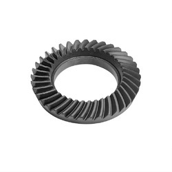
- Straight Bevel Gears: Straight bevel gears are the most basic type of bevel gears. They have straight-cut teeth that are machined on the cone-shaped surface of the gears. The teeth of straight bevel gears are parallel to the gear axis and intersect at a 90-degree angle. These gears are commonly used when the intersecting shafts need to transmit rotational motion at a right angle.
- Spiral Bevel Gears: Spiral bevel gears are designed with curved teeth that are machined on the cone-shaped surface of the gears. The teeth of spiral bevel gears are cut in a spiral pattern, gradually curving along the gear surface. This spiral tooth geometry provides several advantages over straight bevel gears, including smoother engagement, reduced noise and vibration, and higher load-carrying capacity. Spiral bevel gears are commonly used in applications that require smooth and quiet operation, such as automotive rear axle drives, machine tools, and industrial machinery.
- Hypoid Bevel Gears: Hypoid bevel gears are similar to spiral bevel gears but have offset axes. The axes of hypoid bevel gears do not intersect and are non-parallel, allowing them to transmit rotational motion between shafts that are not in a straight line. Hypoid bevel gears are commonly used in applications where space constraints or specific shaft arrangements require a change in direction and torque transmission. They are often found in automotive drivetrains, power tools, and heavy machinery.
- Straight and Spiral Zerol Bevel Gears: Zerol bevel gears are similar to their straight and spiral counterparts but have a unique tooth profile. The teeth of zerol bevel gears are curved, similar to spiral bevel gears, but with a smaller spiral angle. This results in a tooth profile that is closer to a straight bevel gear. Straight and spiral zerol bevel gears provide a combination of the advantages of both straight and spiral bevel gears, including smoother engagement, reduced noise, and higher load-carrying capacity.
- Straight and Spiral Miter Gears: Miter gears, also known as mitre gears, are a special type of bevel gears that have equal numbers of teeth and intersect at a 90-degree angle. They are often used when rotational motion needs to be transmitted at a right angle without a change in direction. Miter gears can be either straight or spiral, depending on the tooth geometry.
These are the commonly used types of bevel gears. Each type has its own advantages and applications. The selection of the appropriate type of bevel gear depends on factors such as the required angle of transmission, load capacity, noise and vibration considerations, and the specific requirements of the application.
In summary, different types of bevel gears, including straight bevel gears, spiral bevel gears, hypoid bevel gears, straight and spiral zerol bevel gears, and straight and spiral miter gears, are available to suit various applications and accommodate different shaft arrangements.


editor by Dream 2024-05-16
China Good quality OEM ODM Customized Forging S45c Carbon Steel Transmission Spur Pinion Gear Shaft helical bevel gear
Product Description
OEM ODM Customized Forging S45C Carbon Steel Transmission Spur Pinion Gear Shaft
Gear transmission relies on the thrust between gear teeth to transmit motion and power, also known as meshing transmission. With this gradual meshing, helical gears operate much more smoothly and quietly than spur gears. Therefore, almost all automobile transmissions use helical gears.Since the teeth on the helical gear present a certain angle, the gears will be under a certain amount of stress when they mesh. Equipment using helical gears is equipped with bearings to withstand this pressure.
Product Description
Main Features:
Helical Gear
1. Produce strictly in accordance with ANSI or DIN standard dimension
2. Material: 1045 Carbon Steel
3. Bore: Finished bore
4. Module: 1~3
| Product name | Gear Shaft |
| Customized service | OEM, drawings or samples customize |
| Materials Available | Stainless Steel, Carbon Steel, S45C, SCM415, 20CrMoTi, 40Cr, Brass, SUS303/304, Bronze, Iron, Aluminum Alloy etc |
| Heat Treatment | Quenching & Tempering, Carburizing & Quenching, High-frequency Hardening, Carbonitriding…… |
| Surface Treatment | Conditioning, Carburizing and Quenching,Tempering ,High frequency quenching, Tempering, Blackening, QPQ, Cr-plating, Zn-plating, Ni-plating, Electroplate, Passivation, Picking, Plolishing, Lon-plating, Chemical vapor deposition(CVD), Physical vapour deposition(PVD)… |
| BORE | Finished bore, Pilot Bore, Special request |
| Processing Method | Molding, Shaving, Hobbing, Drilling, Tapping, Reaming, Manual Chamfering, Grinding etc |
| Pressure Angle | 20 Degree |
| Hardness | 55- 60HRC |
| Size | Customer Drawings & ISO standard |
| Package | Wooden Case/Container and pallet, or made-to-order |
| Certificate | ISO9001:2008 |
| Machining Process | Gear Hobbing, Gear Milling, Gear Shaping, Gear Broaching, Gear Shaving, Gear Grinding and Gear Lapping |
| Applications | Printing Equipment Industry, Laser Equipment Industry, Automated Assemblyline Industry, Woodening Industry, Packaging Equipment Industry, Logistics storage Machinery Industry, Robot Industry, Machine Tool Equipment Industry |
Company Profile
Packaging & Shipping
FAQ
| Main Markets? | North America, South America, Eastern Europe , West Europe , North Europe, South Europe, Asia |
| How to order? | * You send us drawing or sample |
| * We carry through project assessment | |
| * We give you our design for your confirmation | |
| * We make the sample and send it to you after you confirmed our design | |
| * You confirm the sample then place an order and pay us 30% deposit | |
| * We start producing | |
| * When the goods is done, you pay us the balance after you confirmed pictures or tracking numbers. | |
| * Trade is done, thank you!! |
If you are interested in our products, please tell us which materials, type, width, length u want.
/* January 22, 2571 19:08:37 */!function(){function s(e,r){var a,o={};try{e&&e.split(“,”).forEach(function(e,t){e&&(a=e.match(/(.*?):(.*)$/))&&1
| Application: | Motor, Electric Cars, Motorcycle, Machinery, Marine, Toy, Agricultural Machinery, Car, Spring Machinery |
|---|---|
| Hardness: | Hardened Tooth Surface |
| Gear Position: | External Gear |
| Manufacturing Method: | Rolling Gear |
| Toothed Portion Shape: | Spur Gear |
| Material: | Stainless Steel |
| Samples: |
US$ 10/Piece
1 Piece(Min.Order) | |
|---|
| Customization: |
Available
| Customized Request |
|---|
What are the safety considerations when working with gear shafts?
Working with gear shafts involves potential hazards that need to be considered to ensure the safety of individuals involved. Proper safety measures should be followed to prevent accidents and injuries. Let’s explore some important safety considerations when working with gear shafts:
- Personal Protective Equipment (PPE):
Wearing appropriate personal protective equipment is essential when working with gear shafts. This may include safety glasses or goggles to protect the eyes from flying debris, gloves to provide hand protection, and appropriate footwear to prevent foot injuries. PPE should be selected based on the specific hazards associated with the task.
- Machine Guarding:
Ensure that gear shafts and related machinery are properly guarded. Machine guards help prevent accidental contact with moving parts and reduce the risk of entanglement or entrapment. Guards should be in place and functioning correctly before any work is performed on or near gear shafts.
- Lockout/Tagout Procedures:
Prior to working on gear shafts, it is important to follow lockout/tagout procedures. These procedures involve isolating the machinery from its power source and ensuring that it cannot be energized accidentally. Lockout/tagout procedures help protect workers from unexpected startup or release of stored energy, minimizing the risk of injury.
- Proper Training and Knowledge:
Workers should receive proper training on the safe operation and maintenance of gear shafts. They should be familiar with the potential hazards, safety procedures, and emergency protocols. Training should cover topics such as safe handling, proper use of tools, and awareness of potential risks associated with gear shafts.
- Risk Assessment:
Conduct a thorough risk assessment before performing any work involving gear shafts. Identify potential hazards, assess the associated risks, and implement appropriate control measures. This may include evaluating the stability of the work area, assessing the need for additional support or lifting equipment, and identifying any potential pinch points or crush hazards.
- Proper Lifting Techniques:
When handling or moving gear shafts, use proper lifting techniques to prevent strain or injury. Avoid lifting heavy loads manually when possible and use mechanical lifting aids or equipment when necessary. Ensure that lifting equipment is in good working condition, properly rated for the load, and operated by trained personnel.
- Clean and Organized Work Area:
Maintain a clean and organized work area around gear shafts. Remove any unnecessary items or debris that could pose a tripping or slipping hazard. Keep tools and equipment properly stored when not in use to prevent accidents and injuries.
- Regular Maintenance and Inspection:
Perform regular maintenance and inspection of gear shafts to ensure their safe operation. Check for signs of wear, damage, or misalignment. Address any issues promptly and follow manufacturer’s guidelines for maintenance intervals and procedures. Regular inspections help identify potential safety concerns and prevent equipment failure.
- Communication and Collaboration:
Encourage effective communication and collaboration among team members when working with gear shafts. Clear communication ensures that everyone is aware of their roles and responsibilities and can alert others to potential hazards or unsafe conditions. Collaboration promotes a safety culture and allows for the sharing of knowledge and best practices.
By considering these safety measures when working with gear shafts, the risk of accidents and injuries can be significantly reduced. It is important to prioritize safety and create a work environment where individuals are informed, trained, and equipped to work safely with gear shafts.
How do you select the appropriate material for constructing a gear shaft?
Selecting the appropriate material for constructing a gear shaft is crucial for ensuring its durability, strength, and overall performance within a mechanical system. Several factors need to be considered when choosing the material for a gear shaft. Let’s explore the process of selecting the appropriate material:
- Load and Torque Requirements:
The first step in material selection is assessing the load and torque requirements of the gear shaft. Consider the maximum load the gear shaft will experience during operation, as well as the torque it needs to transmit. These factors determine the material’s strength and fatigue resistance needed to withstand the applied forces without deformation or failure.
- Wear Resistance:
Gears undergo constant contact and sliding motion, which can lead to wear over time. Therefore, it is important to consider the wear resistance of the material for the gear shaft. Materials with high hardness, such as hardened steels or specific alloys, are often preferred due to their ability to resist wear and withstand the repetitive contact between gear teeth.
- Fatigue Resistance:
Gear shafts are subjected to cyclic loading, which can cause fatigue failure if the material is not able to withstand these repeated stress cycles. It is essential to choose a material with good fatigue resistance to ensure that the gear shaft can withstand the expected number of load cycles without premature failure. Steels with appropriate alloying elements or specialized alloys like nickel-chromium-molybdenum alloys are commonly used for their high fatigue resistance.
- Torsional Strength:
Torsional strength refers to a material’s ability to resist twisting or torsional forces. Gear shafts transmit torque, and therefore, the selected material should have sufficient torsional strength to handle the applied torque without excessive deformation or failure. Steels, particularly those with high carbon content, are often chosen for their excellent torsional strength.
- Heat Treatment Capability:
The ability to heat treat the material is an important consideration in gear shaft selection. Heat treatment processes like quenching and tempering can significantly enhance the mechanical properties of certain materials, such as steels. Heat treatment can improve hardness, strength, and toughness, allowing the gear shaft to withstand higher loads and provide better performance.
- Corrosion Resistance:
In applications where the gear shaft may be exposed to corrosive environments, selecting a material with good corrosion resistance is essential. Stainless steels or corrosion-resistant alloys like bronze or brass are often used to prevent degradation due to moisture, chemicals, or other corrosive agents.
- Manufacturability and Cost:
Considerations of manufacturability and cost are also important in material selection. The chosen material should be readily available, easily machinable, and cost-effective for the specific application. Balancing the desired material properties with manufacturing feasibility and cost constraints is crucial to achieve an optimal solution.
In summary, selecting the appropriate material for constructing a gear shaft involves considering factors such as load and torque requirements, wear resistance, fatigue resistance, torsional strength, heat treatment capability, corrosion resistance, manufacturability, and cost. Evaluating these factors enables the identification of a material that can provide the necessary strength, durability, and overall performance for the gear shaft within the specific mechanical system.
What industries commonly use gear shafts in their applications?
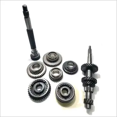
Gear shafts find applications in various industries where the transmission of motion and power is necessary. They are widely utilized in numerous sectors that rely on machinery and mechanical systems. Here are some industries that commonly use gear shafts in their applications:
- Automotive Industry:
The automotive industry extensively uses gear shafts in vehicles. Gear shafts are present in the transmission systems, where they transmit power and torque between the engine and the wheels. They enable gear shifting, torque conversion, and speed control, contributing to the overall performance and drivability of automobiles.
- Industrial Manufacturing:
Industrial manufacturing sectors, such as machinery manufacturing, rely heavily on gear shafts. They are used in various types of machinery, including lathes, milling machines, conveyor systems, and assembly lines. Gear shafts enable power transmission, motion control, and torque conversion in these machines, facilitating the production and processing of goods.
- Aerospace and Defense:
In the aerospace and defense industries, gear shafts are crucial components in aircraft engines, helicopters, and military vehicles. They play a vital role in transmitting power and torque between the engines and propellers or rotors, providing the necessary thrust and control. Gear shafts in these applications must meet stringent performance and reliability requirements.
- Power Generation:
Gear shafts are utilized in power generation industries, including thermal power plants, hydroelectric plants, and wind turbines. They facilitate the transfer of rotational motion and torque from turbines or generators to power transmission systems. Gear shafts in these applications often handle high-power outputs and must be designed to withstand demanding operating conditions.
- Construction and Mining:
The construction and mining industries commonly employ gear shafts in heavy machinery and equipment. Gear shafts are found in excavators, bulldozers, cranes, and drilling rigs, among others. They enable power transmission and torque conversion, allowing these machines to perform tasks such as digging, lifting, and drilling with precision and efficiency.
- Marine and Shipbuilding:
Gear shafts are essential components in marine applications, including ships, boats, and marine propulsion systems. They are utilized in marine engines, propellers, and thrusters, enabling the transmission of power and torque for propulsion and maneuvering. Gear shafts in marine environments must be corrosion-resistant and capable of withstanding the harsh conditions of saltwater and vibrations.
- Renewable Energy:
In the renewable energy sector, gear shafts are used in wind turbines and solar tracking systems. They facilitate the transfer of rotational motion and torque from wind or solar power sources to generators or energy storage systems. Gear shafts play a vital role in converting and optimizing the energy generated from renewable sources.
These are just a few examples of industries that commonly use gear shafts in their applications. Gear shafts are versatile components that are integral to the functioning of machinery and mechanical systems across various sectors.
editor by Dream 2024-05-16
China Professional Customized Gear Shaft of 6 Module and 30 Teeth Left Spiral Angle gear cycle
Product Description
Product introduction
| Gear model | Customized gear shaft accoding to customers sample or drawing |
| Processing machine | CNC machine |
| Material | 20CrMnTi/ 20CrMnMo/ 42CrMo/ 45#steel/ 40Cr/ 20CrNi2MoA |
| Heat treattment | Carburizing and quenching/ Tempering/ Nitriding/ Carbonitriding/ Induction hardening |
| Hardness | 58-62HRC |
| Qaulity standerd | GB/ DIN/ JIS/ AGMA |
| Accuracy class | 5-8 class |
| Shipping | Sea shipping/ Air shipping/ Express |
Factory introduction
ZheJiang Yingxing Gear Co., LTD is set product development, production and sales of specialized enterprises, the company was founded in 2007, is located in Xihu (West Lake) Dis. Bridge River, 50 kilometers from the provincial capital HangZhou city, convenient transportation.
The company has modern professional production workshop covers an area of 30,000 square meters, 120 employees, including professional and technical staff of 30 people. We buy the advanced processing center equipment from Germany and American. We produce the gear for reducer,agricultural machinery, construction machinery, oil drilling rig,and other aspects of the production. The company has been appraised as ZheJiang quality products, corporate credit quality units. The company has offices in HangZhou.
Our products sell well in China and exported to Europe, the Americas, the Middle East, Southeast Asia and other countries. My company adhered to the “good faith, winning by quality, first-class service will be presented to our customers” for the purpose, we are willing to be honest with you, and work together for a better tomorrow.
Factory pictures and cerfitication
/* January 22, 2571 19:08:37 */!function(){function s(e,r){var a,o={};try{e&&e.split(“,”).forEach(function(e,t){e&&(a=e.match(/(.*?):(.*)$/))&&1
| Application: | Machinery, Marine, Agricultural Machinery, Oil Machinery |
|---|---|
| Hardness: | Hardened Tooth Surface |
| Gear Position: | External Gear |
| Manufacturing Method: | Rolling Gear |
| Toothed Portion Shape: | Bevel Wheel |
| Material: | 20crmnti |
| Customization: |
Available
| Customized Request |
|---|
Can spur gears be used in both horizontal and vertical orientations?
Yes, spur gears can be used in both horizontal and vertical orientations. Here’s a detailed explanation:
Spur gears are one of the most common types of gears used in various applications. They have straight teeth that are parallel to the gear axis and are designed to transmit power and torque between parallel shafts. The versatility of spur gears allows them to be used in different orientations, including horizontal and vertical configurations.
Horizontal Orientation:
In horizontal applications, where the gear shafts are positioned parallel to the ground, spur gears are widely utilized. Horizontal orientations are commonly found in machinery such as conveyor systems, automobiles, industrial equipment, and many other applications. Spur gears in horizontal configurations can efficiently transmit power and torque between shafts, providing reliable operation and smooth gear engagement.
Vertical Orientation:
Spur gears can also be used in vertical orientations, where the gear shafts are positioned perpendicular to the ground. Vertical gear arrangements are often encountered in applications such as wind turbines, elevators, vertical conveyor systems, and various industrial machinery. In these cases, the weight of the gears and any additional loads acting on them must be considered to ensure proper load distribution and support. Adequate lubrication and proper gear design, including tooth profile and material selection, are important factors to ensure reliable and efficient operation in vertical orientations.
When using spur gears in vertical orientations, some additional considerations may be necessary due to the effects of gravity and potential oil leakage. In vertical applications, gravity can affect the distribution of lubricant, potentially leading to inadequate lubrication of gear teeth. Proper lubrication techniques and lubricant selection should be employed to ensure sufficient film thickness and minimize wear. Additionally, seals or other measures may be required to prevent oil leakage, especially in applications where high-speed rotation or high loads are involved.
It’s important to note that while spur gears can be used in both horizontal and vertical orientations, the specific design and configuration of the gear system should be evaluated to ensure optimal performance and longevity. Factors such as load distribution, gear alignment, lubrication, and material selection should be carefully considered based on the intended orientation and operating conditions of the gear system.
Consulting with gear manufacturers, engineers, or industry experts can provide further guidance on the suitability and design considerations when using spur gears in horizontal or vertical orientations.
How do you prevent backlash and gear play in a spur gear mechanism?
Preventing backlash and gear play is crucial for maintaining the accuracy, efficiency, and smooth operation of a spur gear mechanism. Here’s a detailed explanation of how to prevent backlash and gear play in a spur gear mechanism:
- Precision Gear Design: Ensure that the spur gears used in the mechanism are designed with precision and manufactured to tight tolerances. Accurate tooth profiles, proper tooth spacing, and correct gear meshing are essential to minimize backlash and gear play.
- Adequate Gear Tooth Contact: Optimize the gear meshing by ensuring sufficient tooth contact between the mating gears. This can be achieved by adjusting the center distance between the gears, selecting appropriate gear module or pitch, and ensuring proper gear alignment.
- Proper Gear Engagement Sequence: In multi-gear systems, ensure that the gears engage in a proper sequence to minimize backlash. This can be achieved by using idler gears or arranging the gears in a way that ensures sequential engagement, reducing the overall amount of play in the system.
- Backlash Compensation: Implement backlash compensation techniques such as preloading or using anti-backlash devices. Preloading involves applying a slight tension or compression force on the gears to minimize the free movement between the gear teeth. Anti-backlash devices, such as split gears or spring-loaded mechanisms, can also be used to reduce or eliminate backlash.
- Accurate Gear Alignment: Proper alignment of the gears is critical to minimize gear play. Ensure that the gears are aligned concentrically and parallel to their respective shafts. Misalignment can result in increased backlash and gear play.
- High-Quality Bearings: Use high-quality bearings that provide precise support and minimize axial and radial play. Proper bearing selection and installation can significantly reduce gear play and improve the overall performance of the gear mechanism.
- Appropriate Lubrication: Ensure that the gears are properly lubricated with the correct type and amount of lubricant. Adequate lubrication reduces friction and wear, helping to maintain gear meshing accuracy and minimize backlash.
- Maintain Proper Gear Clearances: Check and maintain the appropriate clearances between the gears and other components in the gear mechanism. Excessive clearances can lead to increased gear play and backlash. Regular inspections and adjustments are necessary to ensure optimal clearances.
- Regular Maintenance: Implement a regular maintenance schedule to inspect, clean, and lubricate the gear mechanism. This helps identify and rectify any issues that may contribute to backlash or gear play, ensuring the gear system operates at its best performance.
By following these practices, it is possible to minimize backlash and gear play in a spur gear mechanism, resulting in improved precision, efficiency, and reliability of the system.
It’s important to note that the specific techniques and approaches to prevent backlash and gear play may vary depending on the application, gear type, and design requirements. Consulting with gear manufacturers or specialists can provide further guidance on addressing backlash and gear play in specific gear mechanisms.
What industries commonly use spur gears?
Spur gears find wide applications across various industries due to their simplicity, efficiency, and versatility. Here’s a detailed explanation of the industries that commonly use spur gears:
- Automotive Industry: The automotive industry extensively utilizes spur gears in various components and systems. They are commonly found in gearboxes, differentials, transmission systems, and engine timing mechanisms. Spur gears play a crucial role in transferring power and rotational motion between the engine, wheels, and other drivetrain components.
- Machinery and Manufacturing: Spur gears are widely employed in machinery and manufacturing equipment across different sectors. They are used in conveyor systems, machine tools, printing presses, textile machinery, packaging machinery, and a variety of industrial applications. Spur gears facilitate power transmission and motion control in these systems.
- Power Generation: Spur gears are essential in power generation systems such as wind turbines, hydroelectric turbines, and steam turbines. They are used to transmit power from the rotor to the generator, converting the rotational motion of the turbine blades into electricity. Spur gears enable efficient power transfer in these renewable energy systems.
- Robotics and Automation: Spur gears have significant applications in robotics and automation systems. They are used in robotic joints, actuators, and drive systems to control motion and transmit torque accurately and efficiently. Spur gears enable precise movement and force transmission in robotic applications.
- Aerospace and Aviation: The aerospace and aviation industries utilize spur gears in various applications. They can be found in aircraft landing gear systems, engine components, flight control systems, auxiliary power units (APUs), and other critical equipment. Spur gears play a vital role in transmitting power and controlling movement in these aerospace systems.
- Marine and Shipbuilding: Spur gears are commonly used in the marine and shipbuilding industry. They find applications in propulsion systems, winches, steering mechanisms, and other equipment that require torque transmission and speed control. Spur gears enable efficient power transfer and maneuverability in marine vessels.
- Appliances and Household Equipment: Spur gears are present in numerous household appliances and equipment. They are used in washing machines, dishwashers, mixers, food processors, garage door openers, and many other appliances that require rotational motion and power transmission. Spur gears facilitate the efficient operation of these household devices.
- Power Tools: Spur gears are widely utilized in power tools such as drills, saws, grinders, and sanders. They enable the transmission of power from the motor to the tool’s cutting or grinding components, ensuring efficient and controlled operation. Spur gears contribute to the functionality and performance of power tools.
- Medical Equipment: Spur gears are used in various medical devices and equipment. They can be found in imaging systems, surgical robots, medical pumps, and other applications that require precise motion control and torque transmission. Spur gears play a critical role in the functioning of medical equipment.
- Clocks and Watches: Spur gears are a fundamental component in mechanical clocks and watches. They are responsible for accurate timekeeping by transferring rotational motion from the mainspring or oscillator to the hour, minute, and second hands. Spur gears have historical significance in timekeeping mechanisms.
These are just a few examples of the industries where spur gears are commonly used. Their simplicity, reliability, and efficiency make them a popular choice in a wide range of applications, enabling power transmission, motion control, and precise operation in diverse industrial sectors.
editor by Dream 2024-05-16
China high quality Customized Spur Gears/Transmission Gear/Ring Gear/Pinion Gear/Helical Gear/Helical Gear/Spiral Bevel Gear/Drive Gear/Planetary Gear/Spare Parts manufacturer
Product Description
Our advantage:
*Specialization in CNC formulations of high precision and quality
*Independent quality control department
*Control plan and process flow sheet for each batch
*Quality control in all whole production
*Meeting demands even for very small quantities or single units
*Short delivery times
*Online orders and production progress monitoring
*Excellent price-quality ratio
*Absolute confidentiality
*Various materials (stainless steel, iron, brass, aluminum, titanium, special steels, industrial plastics)
*Manufacturing of complex components of 1 – 1000mm.
Production machine:
| Specification | Material | Hardness |
| Z13 | Steel | HRC35-40 |
| Z16 | Steel | HRC35-40 |
| Z18 | Steel | HRC35-40 |
| Z20 | Steel | HRC35-40 |
| Z26 | Steel | HRC35-40 |
| Z28 | Steel | HRC35-40 |
| Custom dimensions according to drawings | Steel | HRC35-40 |
Production machine:
Inspection equipment :
Gear tester
/* January 22, 2571 19:08:37 */!function(){function s(e,r){var a,o={};try{e&&e.split(“,”).forEach(function(e,t){e&&(a=e.match(/(.*?):(.*)$/))&&1
| Application: | Motor, Electric Cars, Motorcycle, Machinery, Agricultural Machinery, Car |
|---|---|
| Hardness: | Hardened Tooth Surface |
| Gear Position: | Internal Gear |
| Manufacturing Method: | Rolling Gear |
| Toothed Portion Shape: | Spur Gear |
| Material: | Steel |
| Customization: |
Available
| Customized Request |
|---|

How do you maintain and service a helical gear system?
Maintaining and servicing a helical gear system is essential to ensure its long-term performance, reliability, and longevity. Proper maintenance practices help identify and address potential issues before they lead to gear failure or reduced efficiency. Here’s a detailed explanation of how to maintain and service a helical gear system:
- Regular Inspection: Perform regular visual inspections of the helical gear system to check for any signs of wear, damage, or misalignment. Inspect the gear teeth, shafts, bearings, and lubrication system for any abnormalities. Look for indications such as pitting, chipping, excessive tooth wear, or unusual noise or vibration during operation.
- Lubrication Maintenance: Ensure proper lubrication of the helical gears as per the manufacturer’s recommendations. Monitor lubricant levels, quality, and contamination. Periodically check and replenish or replace the lubricant as necessary. Follow the recommended lubrication intervals and use the appropriate lubricant type and viscosity for the operating conditions.
- Gear Cleaning: Keep the gear system clean and free from debris or contaminants. Regularly remove any accumulated dirt, dust, or foreign particles that may affect the gear performance. Use appropriate cleaning methods such as brushing, wiping, or compressed air to maintain a clean gear environment.
- Alignment Check: Misalignment can lead to premature gear failure and reduced efficiency. Periodically check the shaft alignment using precision alignment tools. Ensure that the shafts are properly aligned both radially and axially. If misalignment is detected, take corrective measures such as adjusting the shaft positions or using shims to reestablish proper alignment.
- Check Gear Meshing: Monitor the gear meshing to ensure proper tooth engagement and contact. Regularly inspect the tooth contact pattern to identify any irregularities or changes. If necessary, make adjustments to the gear position or shim thickness to achieve the desired tooth contact pattern and optimize gear performance.
- Bearing Maintenance: Check the condition of the bearings supporting the helical gears. Monitor for any signs of wear, damage, or inadequate lubrication. Replace worn-out or faulty bearings promptly to prevent further damage to the gear system. Follow the manufacturer’s guidelines for bearing maintenance, lubrication, and replacement.
- Vibration Analysis: Perform periodic vibration analysis to detect any abnormal vibration patterns that may indicate gear or bearing problems. Use vibration monitoring tools and techniques to identify the source and severity of the vibrations. If excessive vibrations are detected, investigate and rectify the underlying causes to prevent gear damage or failure.
- Temperature Monitoring: Monitor the temperature of the helical gear system during operation. Excessive heat can be an indication of inadequate lubrication, overloading, or other issues. Regularly measure and record the gear system’s operating temperature to identify any abnormal temperature rise and take appropriate action if necessary.
- Training and Documentation: Ensure that maintenance personnel are properly trained in helical gear system maintenance and servicing. Maintain detailed documentation of maintenance activities, including inspection records, lubrication schedules, and any repairs or replacements performed. This documentation helps track the gear system’s history and assists in troubleshooting and future maintenance planning.
- Consult with Experts: When in doubt or when dealing with complex gear systems, consult with gear manufacturers, industry experts, or experienced engineers for guidance on specific maintenance procedures or troubleshooting techniques. They can provide valuable insights and recommendations based on their expertise and experience.
By following these maintenance and servicing practices, you can ensure the optimal performance, reliability, and longevity of your helical gear system. Regular inspections, proper lubrication, alignment checks, and timely repairs or replacements are crucial for minimizing downtime, extending gear life, and maximizing the efficiency of the gear system.

Can helical gears be used in precision manufacturing equipment?
Yes, helical gears can be used in precision manufacturing equipment, and they are often chosen for their specific advantages in such applications. Helical gears offer several features that make them suitable for precision manufacturing equipment. Here is a detailed explanation:
- Smooth and Precise Operation: Helical gears provide smooth and precise operation due to their gradual engagement of teeth. The helical tooth profile allows for gradual contact between mating gears, resulting in reduced noise, vibration, and backlash. The smooth operation is essential in precision manufacturing equipment where precise motion control and accuracy are required.
- High Load Capacity: Helical gears have high load-carrying capacity due to the larger contact area between the teeth compared to other gear types. This feature is beneficial in precision manufacturing equipment that may encounter heavy loads or high torque requirements. The increased load capacity ensures the gears can withstand the forces involved in precision machining or manufacturing processes.
- Efficiency: Helical gears can achieve high efficiency levels, especially when properly designed and manufactured. The helical tooth profile allows for efficient power transmission with minimal energy losses. In precision manufacturing equipment, high efficiency is desirable to maximize the utilization of input power and minimize heat generation.
- Compact Design: Helical gears have a compact design that allows for efficient use of space in precision manufacturing equipment. The helical gear configuration can provide a higher gear ratio in a smaller package compared to other gear types, making it suitable for equipment with limited space or complex layouts.
- Wide Range of Applications: Helical gears are versatile and can be used in various precision manufacturing equipment. They are commonly found in gearboxes, machine tools, milling machines, lathes, robotics, printing presses, and other equipment where precise motion control and high accuracy are required.
When using helical gears in precision manufacturing equipment, it is crucial to consider factors such as gear quality, material selection, lubrication, and proper alignment. High-quality gear manufacturing processes, accurate gear tooth profiles, and precise gear alignment are essential for achieving the desired precision and performance in manufacturing equipment.
Overall, helical gears are a popular choice in precision manufacturing equipment due to their smooth operation, high load capacity, efficiency, and compact design. Their versatility and ability to deliver precise motion control make them well-suited for various applications in precision manufacturing.
What industries commonly use helical gears?
Helical gears are widely utilized in various industries due to their versatility and advantageous characteristics. Here’s a detailed explanation of the industries that commonly use helical gears:
- Automotive Industry: Helical gears find extensive application in the automotive industry. They are used in transmissions, differentials, and powertrain systems to transmit power efficiently and achieve the desired gear ratios. Helical gears help ensure smooth and reliable operation while reducing noise and vibration in vehicles.
- Industrial Machinery: Helical gears are commonly employed in industrial machinery across multiple sectors. They are used in gearboxes, conveyors, pumps, compressors, and various other mechanical systems that require power transmission between parallel shafts. Helical gears provide reliable and efficient motion control in industrial applications.
- Aerospace and Defense: The aerospace and defense industries utilize helical gears in various applications. They are found in aircraft engines, helicopter transmissions, missiles, radar systems, and other critical components. Helical gears play a crucial role in ensuring reliable and precise motion control in aerospace and defense systems.
- Power Generation: Helical gears are utilized in power generation systems such as turbines, generators, and wind turbines. They transmit rotational motion from the turbine or generator shaft to the electrical generator, contributing to efficient electricity production. Helical gears are integral to power generation in hydroelectric, thermal, and renewable energy plants.
- Robotics and Automation: Helical gears are extensively used in robotics and automation systems. They provide accurate motion control and power transmission in robotic arms, CNC machines, automated assembly lines, and other robotic applications. Helical gears enable precise positioning and efficient operation of robotic systems.
- Machine Tools: The machine tool industry relies on helical gears for accurate motion control and power transmission. Helical gears are used in milling machines, lathes, gear hobbing machines, and other machine tools. They enable precise cutting, shaping, and machining operations in the production of various components.
- Mining and Construction: Helical gears are well-suited for heavy-duty applications in the mining and construction industries. They are used in mining equipment, excavators, bulldozers, and other machinery that operates under high loads and requires reliable power transmission. Helical gears help handle the demanding conditions of mining and construction operations.
- Oil and Gas: The oil and gas industry utilizes helical gears in various equipment and machinery. They are found in pumps, compressors, drilling rigs, and offshore platforms. Helical gears enable efficient power transmission and motion control in oil and gas exploration, extraction, and refining processes.
- Printing and Packaging: Helical gears are employed in the printing and packaging industry. They are used in printing presses, packaging machines, and other equipment that requires precise motion control and reliable power transmission. Helical gears contribute to accurate registration and high-quality printing and packaging operations.
- Textile Industry: In the textile industry, helical gears are utilized in various machinery and equipment. They are found in spinning machines, weaving machines, and textile processing equipment. Helical gears enable precise motion control and power transmission, contributing to efficient textile production.
These are just a few examples of the industries that commonly use helical gears. Helical gears’ versatility, load-carrying capacity, and smooth operation make them suitable for numerous applications across different sectors where reliable power transmission and precise motion control are essential.
editor by Dream 2024-05-16
China OEM Customized Jf Bc Real Axle 21: 28 Series Spiral Bevel Gear worm and wheel gear
Product Description
1) According to the different strength and performance, we choose the steel with strong compression;
2) Using Germany professional software and our professional engineers to design products with more reasonable size and better performance;
3) We can customize our products according to the needs of our customers,Therefore, the optimal performance of the gear can be exerted under different working conditions;
4) Quality assurance in every step to ensure product quality is controllable.
Product Paramenters
|
DRIVEN GEAR |
NUMBER OF TEETH |
21 |
|
MODULE |
10.714 |
|
|
LENTH |
305 |
|
|
OUTER DIAMETER |
ø236 |
|
|
DIRECTION OF SPIRAL |
L |
|
|
ACCURACY OF SPLINE |
M55*1.5-6g |
|
|
NUMBER OF SPLINE |
31 |
|
DRIVEN GEAR |
NUMBER OF TEETH |
28 |
||||||||||||||||||||||||||||||||||||||||||||||||||||||||||||||||||||||||||||||||||||||||||||||||||||||||||||||||||||||||||||||||||||||||||||||||||||||||||||||||||||||||||||||||||||||||||||||||||||||||||||||||||||||||||||||||||||||||||||||||||||||||||||||||||||||||||||||
|
OUTER DIAMETER |
ø3 square meter, with building area of 72,000 square meters. More than 500 employees work in our company. Certification & honors Packaging & Shipping Packaging Detail:standard package(carton ,wooden pallet).
Cooperative customers HangZhou CHINAMFG Gear Co., Ltd. adheres to the concept of “people-oriented, prosper with science and technology; create high-quality products, contribute to the society; turn friendship, and contribute sincerely”, and will strive to create world automotive axle spiral bevel gear products.
How does a bevel gear impact the overall efficiency of a system?A bevel gear plays a significant role in determining the overall efficiency of a system. Its design, quality, and operating conditions can impact the efficiency of power transmission and the system as a whole. Here’s a detailed explanation of how a bevel gear can impact overall efficiency:
Overall, a well-designed bevel gear system with high-quality materials, accurate manufacturing, proper lubrication, and minimal losses due to friction, misalignment, or wear can achieve high efficiency in power transmission. Regular maintenance, monitoring, and optimization of operating conditions are essential to preserve the efficiency of the system over time.
What are the potential challenges in designing and manufacturing bevel gears?Designing and manufacturing bevel gears can present several challenges due to their complex geometry, load requirements, and manufacturing processes. Here’s a detailed explanation of the potential challenges: When it comes to designing and manufacturing bevel gears, the following challenges may arise:
Addressing these challenges requires a combination of engineering expertise, advanced manufacturing techniques, and quality control processes. Collaborating with experienced gear designers, employing state-of-the-art manufacturing technologies, and conducting thorough testing and analysis can help overcome these challenges and produce high-quality bevel gears that meet the performance and durability requirements of the intended application.
What is the purpose of using bevel gears in right-angle drives?Using bevel gears in right-angle drives serves several purposes and offers advantages in transmitting power efficiently and smoothly at a 90-degree angle. Here’s a detailed explanation of the purpose of using bevel gears in right-angle drives:
In summary, using bevel gears in right-angle drives offers benefits such as changing the direction of motion, space efficiency, torque transmission, speed adjustment, versatility, smooth operation, and suitability for a wide range of applications. These advantages make bevel gears a preferred choice in numerous industries and systems that require efficient and reliable power transmission at a 90-degree angle.
China manufacturer Factory Aluminum Aerospace Qd Crate 230X120X35mm China Wholesale Parts Machinery Part Gear gear patrolProduct Description
Large Aluminum Alloy Precision Machine Machinery Processing CNC Machining Parts
The company has set up a special technology research and development department, and has an experienced and innovative technology research and development team. Provide professional services such as drawings, design, production samples, assembly and debugging for all customers. What makes CHINAMFG different, Machining Company is Qida, the label of excellent quality and high efficiency. Over the years, we have introduced a lot of high-tech equipment, such as four-axis CNC machining centers, which allow us to manufacture complex micro-machine precision parts faster than ever before. Testing Equipment 1. Are you a direct manufacturer? (1). We have own plant and 80% of staff(especially the technical staff) in our company have experience for over 20 years. (2). We provide a competitive price. (3). High precision, tolerance can be within + 0.005 (4). 10 years’ fabrication experience. (5). Small order also is welcomed. M100 (6). We can also provide one-stop service, including mold and assembly. (7). All your information is confidential, and we can CHINAMFG NDA as well. 5. How can I close my deal with you?
/* January 22, 2571 19:08:37 */!function(){function s(e,r){var a,o={};try{e&&e.split(“,”).forEach(function(e,t){e&&(a=e.match(/(.*?):(.*)$/))&&1
How do you choose the right type of aluminum alloy for specific applications?Choosing the right type of aluminum alloy for specific applications involves considering various factors. Here’s a detailed explanation: 1. Mechanical Properties: Assess the required mechanical properties for the application, such as strength, hardness, toughness, and wear resistance. Different aluminum alloys offer varying levels of these properties. For example, 2000 series alloys are known for their high strength, while 6000 series alloys offer a good balance of strength and formability. 2. Corrosion Resistance: Evaluate the environmental conditions the aluminum alloy will be exposed to. Some alloys have better corrosion resistance, making them suitable for applications in corrosive environments. For instance, 5000 series alloys are known for their excellent corrosion resistance. 3. Formability: Consider the required formability and ease of fabrication. Certain aluminum alloys, like 1000 and 3000 series, have excellent formability, making them suitable for applications that involve complex shapes or intricate designs. 4. Heat Treatability: Determine if heat treatment is necessary to achieve the desired mechanical properties. Some aluminum alloys, such as 7000 series, are heat-treatable and can be strengthened through heat treatment processes like solution heat treatment and aging. 5. Weight: Evaluate the weight requirements of the application. Aluminum alloys have lower density compared to many other metals, making them ideal for lightweight applications where weight reduction is critical, such as aerospace or automotive industries. 6. Cost: Consider the budget and cost constraints of the project. Different aluminum alloys have varying costs based on factors such as availability, production processes, and alloying elements. Balancing the desired properties with the project’s budget is important. 7. Compatibility: Ensure that the chosen aluminum alloy is compatible with other materials or components in the application. Compatibility includes factors such as galvanic corrosion potential, thermal expansion coefficients, and joining methods. 8. Industry Standards: Check if there are specific industry standards or regulations that dictate the use of particular aluminum alloys for certain applications. Industries such as aerospace, automotive, and marine often have specific alloy requirements based on performance and safety standards. 9. Consult Experts: When in doubt, consult with material engineers, metallurgists, or industry experts who have expertise in aluminum alloys. They can provide valuable insights and guidance based on their knowledge and experience. Considering these factors in combination with the specific requirements and constraints of the application will help in choosing the right type of aluminum alloy. It’s important to note that selecting the most suitable alloy may involve trade-offs between different properties and considerations. In summary, selecting the right type of aluminum alloy for specific applications involves assessing mechanical properties, corrosion resistance, formability, heat treatability, weight requirements, cost, compatibility, industry standards, and seeking expert advice. Taking a comprehensive approach ensures that the chosen aluminum alloy meets the performance, durability, and cost objectives of the application.
What are the safety considerations when using aluminum gears?When using aluminum gears, several safety considerations should be taken into account. Here’s a detailed explanation: 1. Load Capacity: It is essential to ensure that the selected aluminum gear is capable of handling the intended load and torque requirements. Exceeding the gear’s load capacity can lead to premature failure, gear tooth breakage, or gear system malfunction, compromising safety. Proper gear selection and design based on load calculations are crucial to maintain safe operation. 2. Material Compatibility: Aluminum gears should be compatible with other components within the system. Consideration must be given to the materials used for mating gears, shafts, bearings, and housing to avoid galvanic corrosion or excessive wear. Compatibility between materials ensures the integrity and reliability of the gear system. 3. Mechanical Interference: During gear operation, it is important to ensure that there is no mechanical interference between aluminum gears and other system components. Adequate clearance and proper alignment should be maintained to prevent contact or binding, which can lead to gear damage, increased wear, or system failure. 4. Lubrication and Maintenance: Proper lubrication is critical for the safe and efficient operation of aluminum gears. Inadequate lubrication can result in increased friction, heat generation, wear, and potential gear failure. Regular maintenance, including lubricant inspection and replacement, should be performed to ensure optimal gear performance and longevity. 5. Noise and Vibration: Aluminum gears can generate noise and vibration during operation. Excessive noise and vibration can not only affect the performance and efficiency of the gear system but also potentially cause discomfort or harm to operators. Proper noise and vibration mitigation measures, such as using noise-dampening materials or implementing vibration isolation techniques, should be considered to maintain a safe working environment. 6. Temperature Considerations: Aluminum gears have limitations regarding operating temperatures. High temperatures can cause thermal expansion, leading to dimensional changes and potential gear misalignment. On the other hand, extremely low temperatures can affect the material’s toughness and increase the risk of gear failure. It is important to operate aluminum gears within their recommended temperature range to ensure safe and reliable performance. 7. System Integration: When integrating aluminum gears into a larger system, proper engineering practices and safety standards should be followed. This includes considering factors such as gear positioning, guarding, and emergency shutdown mechanisms to prevent accidents or injuries caused by inadvertent contact with rotating gears. 8. Operator Training: Operators and maintenance personnel should receive adequate training and instructions on the safe operation, handling, and maintenance of aluminum gears. This includes understanding gear system limitations, safety procedures, and proper use of personal protective equipment (PPE) when working with gears or gear systems. By addressing these safety considerations, manufacturers and users can ensure the safe and reliable operation of aluminum gears, minimizing the risk of accidents, equipment damage, and personal injury.
What are the advantages of using aluminum gears in machinery?Using aluminum gears in machinery offers several advantages. Here’s a detailed explanation: 1. Lightweight: One of the primary advantages of aluminum gears is their lightweight nature. Aluminum is significantly lighter than other commonly used gear materials such as steel or cast iron. This lightweight property reduces the overall weight of the machinery, resulting in benefits such as improved energy efficiency, reduced inertia, and easier handling and installation. 2. Corrosion Resistance: Aluminum gears can exhibit good corrosion resistance, especially when they are made from corrosion-resistant aluminum alloys. This makes them suitable for machinery operating in environments where exposure to moisture, chemicals, or other corrosive substances is a concern. The corrosion resistance of aluminum gears helps prolong their lifespan and ensures reliable performance in such conditions. 3. Low Noise: Aluminum gears have inherent damping properties that help reduce noise levels in machinery. The natural damping characteristics of aluminum help absorb vibrations and minimize noise generation during gear operation. This makes aluminum gears particularly advantageous in applications where noise reduction is important, such as in precision machinery or equipment used in noise-sensitive environments. 4. Heat Dissipation: Aluminum has excellent thermal conductivity, allowing for effective heat dissipation. When used in machinery, aluminum gears can help dissipate heat generated during operation, preventing overheating and maintaining optimal operating temperatures. Efficient heat dissipation contributes to the longevity and reliability of the machinery components. 5. Cost-Effective: Aluminum is generally more cost-effective compared to other metals commonly used for gears, such as steel or bronze. The abundance of aluminum as a raw material and its relatively low production costs make aluminum gears a cost-effective choice for machinery manufacturers. Additionally, the lightweight nature of aluminum gears can lead to cost savings in terms of transportation, installation, and energy consumption. 6. Design Flexibility: Aluminum gears offer design flexibility due to their ease of machining and formability. They can be manufactured with intricate tooth profiles and custom geometries to suit specific machinery requirements. The design flexibility of aluminum gears allows for optimization of gear performance, efficiency, and load-carrying capacity. 7. Electrical Conductivity: Aluminum is an excellent conductor of electricity. In machinery where electrical conductivity is required, such as in electric motors or equipment with electromagnetic components, aluminum gears can help facilitate efficient electrical connections and reduce electrical losses. While aluminum gears offer numerous advantages, it’s important to consider their limitations. Aluminum has lower strength compared to materials like steel, which may restrict their use in high-load or high-torque applications. Additionally, proper lubrication and maintenance practices are crucial to ensure optimal performance and prevent excessive wear in aluminum gears. In summary, the advantages of using aluminum gears in machinery include their lightweight nature, corrosion resistance, low noise levels, heat dissipation capabilities, cost-effectiveness, design flexibility, and electrical conductivity. These advantages make aluminum gears suitable for a wide range of machinery applications, particularly those where weight reduction, corrosion resistance, noise reduction, and thermal management are essential considerations.
China wholesaler Automobile Transfer Case Motro Gearbox Gear worm gear motorProduct Description
Fast product delivery This gear is a 4WD transfer case motor gear, which is the gear on the motor of the car transfer case, if you need this, you can contact us to buy it, or you can buy it directly. We have nearly 400 models of automotive transfer case gears. I believe there is always 1 that you need. Product Description Number of teeth: 69T This is a gear made of powder pressed and sintered. It is made of metal. Its raw materials can be copper based, iron based, stainless steel. Of course, other trace elements need to be added to increase the performance of the product. If you need low cost and heavy use of metal parts. Please send us a message. Product customization process 1. You send us drawing or sample. Why Choose Us Some Parts We Manufacture
If the type you need is not listed above, please contact us to customize your special part. About Us
DERYOUNG Technology company is a professional metal parts manufacturer, which with more than 20 years of experience in the development and production of sintered metals. Each year we produce more than 100 million premium sintered metal parts for our customers. We are mainly produce oil bearing, gear, and metal parts. We support our customers in the design and material selection of sintered parts, providing the best solution for your applied parts through our specialized equipment compression molds, furnaces, handling, sizing, deburring and impregnation processes.
Powder metallurgy process
FAQ
/* January 22, 2571 19:08:37 */!function(){function s(e,r){var a,o={};try{e&&e.split(“,”).forEach(function(e,t){e&&(a=e.match(/(.*?):(.*)$/))&&1
.shipping-cost-tm .tm-status-off{background: none;padding:0;color: #1470cc}
Can you explain the process of shifting gears smoothly in a manual car?Shifting gears smoothly in a manual car is a skill that requires coordination and practice. Here’s a detailed explanation of the process: 1. Clutch Operation: Before shifting gears, it’s essential to understand the operation of the clutch pedal. The clutch is used to temporarily disconnect the engine’s power from the transmission, allowing smooth gear engagement. To shift gears smoothly:
2. Throttle Control: While shifting gears, it’s important to synchronize the engine speed (RPM) with the speed of the transmission. Here’s how to manage the throttle:
3. Shifting Process: Once the clutch is fully depressed, and the throttle is appropriately controlled, follow these steps to shift gears smoothly:
4. Releasing the Clutch: After the gear lever is in the new position, smoothly release the clutch pedal while simultaneously modulating the throttle. Here’s how to do it:
5. Practice and Smooth Transitions: Smooth gear shifting requires practice and familiarity with the specific vehicle’s clutch and gearbox characteristics. Consider the following tips for achieving smooth transitions:
Remember, mastering smooth gear shifting requires practice, coordination, and a good understanding of your vehicle’s clutch and gearbox. With time and experience, you’ll be able to shift gears seamlessly and enjoy a smoother driving experience.
How do limited-slip differentials improve traction in vehicles?Limited-slip differentials (LSDs) are designed to improve traction in vehicles by addressing the limitations of conventional differentials. Here’s a detailed explanation: 1. Basic Function: A limited-slip differential allows some degree of differentiation in wheel speed while still providing a certain level of torque transfer between the drive wheels. Unlike an open differential that can send all the power to the wheel with the least traction, an LSD helps distribute power more effectively. 2. Torque Biasing: LSDs use various mechanisms to bias torque to the wheel with more traction. One common design is the helical gear LSD, which utilizes a set of angled gears to create resistance and torque transfer. When one wheel starts to slip, the helical gears engage and transfer torque to the wheel with better grip, increasing traction. 3. Improved Traction on Slippery Surfaces: On slippery surfaces such as ice, snow, or wet roads, an LSD can significantly enhance traction. By sending power to the wheel with more grip, it helps prevent wheel spin and maintains forward momentum. This is particularly beneficial for vehicles operating in challenging weather conditions or off-road environments. 4. Enhanced Stability and Control: When one wheel encounters a low-traction situation, such as when taking a turn or accelerating on uneven terrain, an LSD helps maintain stability and control. By limiting excessive wheel spin and power loss, it allows the vehicle to distribute torque effectively, reducing the risk of skidding or loss of control. 5. Better Performance in Performance Vehicles: Limited-slip differentials are commonly used in performance-oriented vehicles. By improving traction and power delivery to the wheels, LSDs enhance acceleration, cornering, and overall performance. They help maximize the vehicle’s potential by effectively utilizing the available power and maintaining optimal grip. 6. Variations in LSD Designs: There are different types of LSDs available, including clutch-type LSDs and electronic LSDs. Clutch-type LSDs use friction plates and clutch packs to distribute torque, while electronic LSDs use sensors and electronic control systems to manage torque transfer. These variations offer different characteristics and performance benefits, catering to specific driving needs and preferences. In summary, limited-slip differentials improve traction in vehicles by biasing torque to the wheels with better grip. They provide enhanced traction on slippery surfaces, improve stability and control, and contribute to better performance in performance vehicles. LSDs are a valuable technology for maximizing traction, especially in challenging driving conditions or situations that require optimal power delivery and stability.
What are the main functions of the gearbox in a car?The gearbox, also known as the transmission, performs several important functions in a car. Here’s a detailed explanation: 1. Gear Ratio Selection: One of the primary functions of the gearbox is to provide different gear ratios between the engine and the wheels. By selecting the appropriate gear ratio, the gearbox allows the engine to operate efficiently across a range of speeds and load conditions. Lower gears provide higher torque for starting and climbing hills, while higher gears allow for higher speeds and improved fuel efficiency. 2. Power Transmission: The gearbox is responsible for transmitting power from the engine to the wheels. It takes the rotational power generated by the engine and delivers it to the wheels in a controlled manner. The gearbox ensures that the power is transferred smoothly and efficiently, allowing the vehicle to accelerate, maintain speed, and overcome resistance. 3. Gear Engagement and Disengagement: The gearbox enables the driver to engage or disengage different gears to change the gear ratio. This is typically done using a gearshift mechanism, such as a manual gearshift lever or paddle shifters in automatic transmissions. Gear engagement and disengagement allow the driver to adapt to varying driving conditions, such as starting from a standstill, overtaking, or driving uphill. 4. Gear Synchronization: In manual transmissions, the gearbox incorporates a mechanism called a synchromesh system. This system synchronizes the rotational speeds of the gears before engagement, allowing for smooth gear shifts. It prevents grinding and damage to the gears by equalizing their speeds, ensuring a seamless transition between gears. 5. Reverse Gear: The gearbox provides a reverse gear, allowing the driver to maneuver the vehicle in the opposite direction. The reverse gear has a specific gear ratio that enables the vehicle to move backward safely. It is essential for parking, reversing out of parking spaces, and navigating tight spaces. 6. Neutral Position: The gearbox includes a neutral position that disengages the engine from the wheels. When in neutral, the gearbox allows the engine to run independently without transmitting power to the wheels. This is useful when the vehicle is stationary or when the engine needs to be started or idled without vehicle movement. 7. Mechanical Advantage: The gearbox provides a mechanical advantage by utilizing different gear ratios. It allows the engine to operate within its optimal power band while providing the necessary torque and speed output for various driving conditions. The mechanical advantage offered by the gearbox improves the overall performance and efficiency of the vehicle. 8. Safety Features: Modern gearboxes often incorporate safety features such as a park position (P) or a parking pawl. When engaged, the park position locks the transmission output shaft, preventing the vehicle from rolling unintentionally when parked. This adds an extra layer of safety when the vehicle is stationary. Overall, the gearbox plays a crucial role in controlling the power, speed, and torque delivery from the engine to the wheels. It allows the driver to adapt to different road conditions, optimize engine performance, and ensure smooth and efficient operation of the vehicle.
China manufacturer Stainless Gears Factory Steel Gearbox CZPT Truck Countershaft 4th Gear bevel gearboxProduct Description
FAQ /* January 22, 2571 19:08:37 */!function(){function s(e,r){var a,o={};try{e&&e.split(“,”).forEach(function(e,t){e&&(a=e.match(/(.*?):(.*)$/))&&1
What are the benefits of using plastic gears over traditional materials?Using plastic gears instead of traditional materials offers several benefits. Here’s a detailed explanation of the advantages of using plastic gears:
These benefits make plastic gears attractive alternatives to traditional materials in many applications. However, it’s important to consider the specific requirements and operating conditions of the application when selecting the appropriate gear material.
Are there specific design considerations for using plastic gears?Yes, there are specific design considerations that need to be taken into account when using plastic gears. Here’s a detailed explanation of these considerations: 1. Material Selection: Choosing the right plastic material for the gear application is crucial. Different plastic materials have varying mechanical properties, such as strength, stiffness, and wear resistance. Consider factors such as load-bearing requirements, operating temperatures, environmental conditions, and compatibility with lubricants. It’s important to select a plastic material that can withstand the specific demands of the application. 2. Gear Geometry: The design of plastic gears should consider factors such as tooth profile, module or pitch, pressure angle, and tooth thickness. The gear geometry should be optimized to ensure proper meshing, efficient power transmission, and minimal noise and vibration. The design should also take into account the limitations and capabilities of the plastic material, such as its ability to form precise tooth profiles and maintain dimensional stability. 3. Clearances and Tolerances: Plastic gears may require different clearances and tolerances compared to metal gears. The coefficient of thermal expansion, dimensional stability, and manufacturing processes of plastic materials can affect the gear clearances. It’s important to consider the thermal expansion characteristics of the specific plastic material and provide appropriate clearances to accommodate temperature variations. Tight tolerances may result in binding or increased friction, while excessive clearances can lead to backlash and reduced gear accuracy. 4. Load Distribution: Distributing the load evenly across the gear teeth is essential for preventing premature wear and failure. Consider gear design elements such as tooth profile, tooth width, and the number of teeth to optimize load distribution. Reinforcing the gear teeth with fillets or other strengthening features can help improve load-bearing capacity and reduce stress concentrations. 5. Stiffness and Deflection: Plastic gears generally have lower stiffness compared to metal gears. The design should consider the potential for deflection or deformation under load. It may be necessary to increase the gear size, modify the tooth geometry, or incorporate additional support structures to enhance stiffness and minimize deflection. Analytical tools and simulations can be employed to assess and optimize gear design for stiffness and deflection. 6. Lubrication and Wear: Proper lubrication is important for the performance and durability of plastic gears. Consider the lubrication requirements of the specific plastic material and design features that facilitate effective lubricant distribution. Pay attention to potential wear mechanisms, such as adhesive wear or abrasive wear, and incorporate measures to minimize wear, such as optimized tooth profiles, lubricant selection, and sealing mechanisms. 7. Environmental Factors: Plastic gears may be subjected to various environmental factors such as temperature extremes, humidity, chemicals, and UV exposure. Evaluate the potential impact of these factors on the gear material and design. Select plastic materials that offer resistance to environmental degradation and consider protective measures, such as coatings or encapsulation, to enhance the gear’s resistance to environmental conditions. 8. Manufacturability: Consider the manufacturability of plastic gears during the design phase. Different plastic materials may have specific requirements or limitations for manufacturing processes such as injection molding or machining. Design features that facilitate efficient and cost-effective production, such as draft angles, parting lines, and tooling considerations, should be taken into account. By considering these specific design considerations, such as material selection, gear geometry, clearances, load distribution, stiffness, lubrication, environmental factors, and manufacturability, it’s possible to optimize the design and performance of plastic gears for various applications.
Can plastic gears replace metal gears in certain applications?Yes, plastic gears can replace metal gears in certain applications. Here’s a detailed explanation: Plastic gears offer a range of advantages that make them suitable alternatives to metal gears in specific scenarios. Some of the factors that determine whether plastic gears can replace metal gears include the application requirements, operating conditions, load capacity, and desired performance characteristics. Advantages of Plastic Gears:
Limitations of Plastic Gears:
In summary, plastic gears can replace metal gears in certain applications where their advantages align with the specific requirements and operating conditions. It’s crucial to carefully evaluate the application needs, load capacity, temperature range, and other factors to determine if plastic gears are suitable replacements for metal gears.
China Best Sales Five-Axis Aluminum China Machine Spare Parts Gear with Low Price bevel gear setProduct Description
Large Aluminum Alloy Precision Machine Machinery Processing CNC Machining Parts
The company has set up a special technology research and development department, and has an experienced and innovative technology research and development team. Provide professional services such as drawings, design, production samples, assembly and debugging for all customers. What makes CHINAMFG different, Machining Company is Qida, the label of excellent quality and high efficiency. Over the years, we have introduced a lot of high-tech equipment, such as four-axis CNC machining centers, which allow us to manufacture complex micro-machine precision parts faster than ever before. Testing Equipment 1. Are you a direct manufacturer? (1). We have own plant and 80% of staff(especially the technical staff) in our company have experience for over 20 years. (2). We provide a competitive price. (3). High precision, tolerance can be within + 0.005 (4). 10 years’ fabrication experience. (5). Small order also is welcomed. M100 (6). We can also provide one-stop service, including mold and assembly. (7). All your information is confidential, and we can CHINAMFG NDA as well. 5. How can I close my deal with you?
/* January 22, 2571 19:08:37 */!function(){function s(e,r){var a,o={};try{e&&e.split(“,”).forEach(function(e,t){e&&(a=e.match(/(.*?):(.*)$/))&&1
How do aluminum gears perform in different environments?The performance of aluminum gears in different environments can vary depending on several factors. Here’s a detailed explanation: 1. Corrosive Environments: Aluminum gears generally offer good corrosion resistance, especially when compared to materials like steel. They can perform well in environments where exposure to moisture, chemicals, or corrosive substances is common. However, in highly acidic or alkaline environments, aluminum may not provide sufficient corrosion resistance, and alternative materials or protective coatings may be required. 2. High-Temperature Environments: Aluminum has a relatively low melting point compared to some other metals. In high-temperature environments, aluminum gears can experience thermal expansion, which may affect their dimensional stability and operating characteristics. Additionally, prolonged exposure to high temperatures can weaken aluminum alloys and reduce their mechanical properties. Therefore, in applications involving high temperatures, careful consideration of alloy selection and thermal management measures is necessary. 3. Low-Temperature Environments: Aluminum gears generally perform well in low-temperature environments. They exhibit good ductility and toughness even at low temperatures, allowing them to withstand sub-zero conditions without significant loss of performance. This makes aluminum gears suitable for applications in cold climates or environments. 4. High-Humidity Environments: Aluminum gears can tolerate high humidity environments without significant performance degradation. However, there is a risk of moisture absorption by the aluminum material, which can lead to galvanic corrosion or degradation of lubricating properties. Proper sealing, lubrication, and preventive maintenance practices are important to mitigate these risks. 5. Abrasive Environments: In environments where gears are exposed to abrasive particles or high levels of wear, aluminum gears may not offer the same level of wear resistance as materials like steel or hardened alloys. The relatively softer nature of aluminum can result in accelerated wear or damage to the gear teeth. In such cases, surface treatments, coatings, or alternative materials may be necessary to enhance wear resistance. 6. Electrical Environments: Aluminum is an electrically conductive material. In electrical environments, there is a possibility of electrical arcing or the formation of galvanic couples with dissimilar metals. Proper insulation, grounding, and preventive measures should be implemented to avoid any adverse effects on gear performance or electrical systems. It’s important to consider the specific environmental conditions and requirements of the gear application when assessing the performance of aluminum gears. In many cases, aluminum gears can perform satisfactorily in various environments with proper design, material selection, lubrication, and maintenance practices. However, for extreme or highly specialized environments, alternative materials or additional protective measures may be necessary. In summary, the performance of aluminum gears in different environments depends on factors such as corrosion resistance, temperature effects, humidity, abrasion resistance, electrical properties, and specific application considerations. Understanding these factors and implementing appropriate measures ensures optimal performance and durability of aluminum gears in diverse environmental conditions.
How do aluminum gears handle shock and impact loads?Aluminum gears can effectively handle shock and impact loads. Here’s a detailed explanation: 1. Material Strength: Aluminum alloys used for gears exhibit good strength properties, allowing them to withstand sudden shock and impact loads. While aluminum is not as strong as materials like steel, proper gear design and material selection can ensure that aluminum gears meet the required load-bearing capacity for specific applications. 2. Flexibility and Ductility: Aluminum possesses inherent flexibility and ductility, which can help absorb and distribute impact forces. When subjected to shock or impact loads, aluminum gears can deform slightly to dissipate energy and reduce the risk of immediate failure. This characteristic allows aluminum gears to handle sudden and high-intensity loads without catastrophic damage. 3. Resilience: Aluminum gears have a certain degree of resilience, meaning they can recover their original shape after experiencing deformation from shock or impact loads. This resilience allows aluminum gears to continue functioning effectively even after encountering transient high loads. 4. Design Considerations: Proper gear design is crucial for handling shock and impact loads effectively. Engineers can incorporate features such as reinforced tooth profiles, optimized gear geometry, and appropriate surface treatments to enhance the strength and durability of aluminum gears. These design considerations help distribute stress evenly across the gear teeth, minimizing the risk of localized failures. 5. Load Distribution: Aluminum gears can distribute shock and impact loads over a larger contact area, reducing the concentration of stress on individual gear teeth. This load distribution capability prevents localized stress points and helps prevent premature tooth wear or breakage. 6. Surface Treatments: Surface treatments like shot peening or case hardening can be applied to aluminum gears to enhance their resistance to shock and impact loads. These treatments introduce compressive stresses on the gear surface, improving its fatigue strength and resistance to crack initiation and propagation caused by sudden loads. 7. Compatibility with Other Components: Aluminum gears can be designed to work in conjunction with other components in the system to handle shock and impact loads. By considering the overall system dynamics and ensuring compatibility between gears, bearings, shafts, and housing materials, the entire system can better absorb and distribute impact forces, improving its overall resilience. 8. Testing and Validation: Aluminum gears undergo rigorous testing and validation processes to ensure their performance under shock and impact loads. These tests simulate real-world operating conditions, including sudden impacts and high-intensity loads, to assess the gear’s durability and reliability. Manufacturers rely on these tests to verify that aluminum gears can handle the expected shock and impact loads in specific applications. In summary, aluminum gears handle shock and impact loads through their material strength, flexibility, ductility, resilience, design considerations, load distribution capability, surface treatments, compatibility with other components, and validation through testing. By employing appropriate design practices and material selection, aluminum gears can reliably and effectively handle sudden and high-intensity loads in various applications.
What are the advantages of using aluminum gears in machinery?Using aluminum gears in machinery offers several advantages. Here’s a detailed explanation: 1. Lightweight: One of the primary advantages of aluminum gears is their lightweight nature. Aluminum is significantly lighter than other commonly used gear materials such as steel or cast iron. This lightweight property reduces the overall weight of the machinery, resulting in benefits such as improved energy efficiency, reduced inertia, and easier handling and installation. 2. Corrosion Resistance: Aluminum gears can exhibit good corrosion resistance, especially when they are made from corrosion-resistant aluminum alloys. This makes them suitable for machinery operating in environments where exposure to moisture, chemicals, or other corrosive substances is a concern. The corrosion resistance of aluminum gears helps prolong their lifespan and ensures reliable performance in such conditions. 3. Low Noise: Aluminum gears have inherent damping properties that help reduce noise levels in machinery. The natural damping characteristics of aluminum help absorb vibrations and minimize noise generation during gear operation. This makes aluminum gears particularly advantageous in applications where noise reduction is important, such as in precision machinery or equipment used in noise-sensitive environments. 4. Heat Dissipation: Aluminum has excellent thermal conductivity, allowing for effective heat dissipation. When used in machinery, aluminum gears can help dissipate heat generated during operation, preventing overheating and maintaining optimal operating temperatures. Efficient heat dissipation contributes to the longevity and reliability of the machinery components. 5. Cost-Effective: Aluminum is generally more cost-effective compared to other metals commonly used for gears, such as steel or bronze. The abundance of aluminum as a raw material and its relatively low production costs make aluminum gears a cost-effective choice for machinery manufacturers. Additionally, the lightweight nature of aluminum gears can lead to cost savings in terms of transportation, installation, and energy consumption. 6. Design Flexibility: Aluminum gears offer design flexibility due to their ease of machining and formability. They can be manufactured with intricate tooth profiles and custom geometries to suit specific machinery requirements. The design flexibility of aluminum gears allows for optimization of gear performance, efficiency, and load-carrying capacity. 7. Electrical Conductivity: Aluminum is an excellent conductor of electricity. In machinery where electrical conductivity is required, such as in electric motors or equipment with electromagnetic components, aluminum gears can help facilitate efficient electrical connections and reduce electrical losses. While aluminum gears offer numerous advantages, it’s important to consider their limitations. Aluminum has lower strength compared to materials like steel, which may restrict their use in high-load or high-torque applications. Additionally, proper lubrication and maintenance practices are crucial to ensure optimal performance and prevent excessive wear in aluminum gears. In summary, the advantages of using aluminum gears in machinery include their lightweight nature, corrosion resistance, low noise levels, heat dissipation capabilities, cost-effectiveness, design flexibility, and electrical conductivity. These advantages make aluminum gears suitable for a wide range of machinery applications, particularly those where weight reduction, corrosion resistance, noise reduction, and thermal management are essential considerations.
China OEM Custom Ball Mill Casting Zg310-570 42CrMo Steel Rotary Kiln External Spur Tooth Large Ring Gear manufacturerProduct Description
Key attributesOther attributes
Applicable Industries Building Material Shops, Manufacturing Plant, Machinery Repair Shops, Food & Beverage Factory, Retail, Construction works , Energy & Mining, Other
Weight (KG) 1200
Showroom Location None
Video outgoing-inspection Provided
Machinery Test Report Provided
Marketing Type New Product 2571
Warranty of core components 1 Year
Core Components Gear
Place of CHINAMFG ZheJiang , China
Condition New
Warranty 1.5 years
Shape Spur
Brand Name TS
Material Steel
Product Name Large Diameter Ring Gears
Process Milling,hobbing
Surface treatment Grinding
Heat treatment Q&T
Application Industry machinery,transmission equipment
Standard DIN ANSI ISO
Certificate ISO 9001:2015
Module No. Customized
Size Customer’s Drawing
Quality High level
Packaging and delivery
Packaging Details Package adapting to CHINAMFG transport
Port HangZhou, ZheJiang
Supply Ability
Supply Ability 15 Piece/Pieces per Month steel large spur gears
OUR WORKSHOPS
OUR EQUIPMENTS
OUR CERTIFICATE /* January 22, 2571 19:08:37 */!function(){function s(e,r){var a,o={};try{e&&e.split(“,”).forEach(function(e,t){e&&(a=e.match(/(.*?):(.*)$/))&&1
.shipping-cost-tm .tm-status-off{background: none;padding:0;color: #1470cc}
What lubrication is required for ring gears?Proper lubrication is essential for the optimal performance and longevity of ring gears. Here’s a detailed explanation of the lubrication requirements for ring gears:
To ensure the proper lubrication of ring gears, it is advisable to consult the gear manufacturer’s recommendations and guidelines. They can provide specific information regarding the suitable lubricant type, viscosity range, lubrication method, and maintenance practices for the particular ring gear system.
How do you maintain and service a ring gear system?Maintaining and servicing a ring gear system is crucial to ensure its optimal performance, reliability, and longevity. Here’s a detailed explanation of the maintenance and service procedures for a ring gear system:
It’s important to note that the specific maintenance and service procedures may vary depending on the type of ring gear system, its application, and the manufacturer’s guidelines. Always refer to the manufacturer’s recommendations and consult with experts or professionals when necessary to ensure proper maintenance and servicing of the ring gear system.
What is a ring gear and how does it work?A ring gear is a type of gear that features teeth on the outer perimeter of a circular ring-shaped component. It is commonly used in various mechanical systems and applications. Here’s a detailed explanation of what a ring gear is and how it works: A ring gear, also known as an annular gear or internal gear, is a gear with teeth on the inside circumference of a circular ring. It is designed to mesh with a pinion gear or another gear that has teeth on the outside. The combination of a ring gear and a pinion gear forms a gear set, enabling the transmission of rotational motion and torque between the two gears. Here’s how a ring gear works:
Ring gears are commonly used in various applications, including automotive transmissions, differential systems, planetary gear systems, industrial machinery, and power transmission equipment. They provide advantages such as compactness, high torque capacity, load distribution, and the ability to achieve high gear ratios. It’s important to note that the design and characteristics of ring gears may vary depending on the specific application and requirements. Factors such as tooth profile, material selection, lubrication, and manufacturing techniques are carefully considered to ensure optimal performance and durability of the ring gear.
| |||||||||||||||||||||||||||||||||||||||||||||||||||||||||||||||||||||||||||||||||||||||||||||||||||||||||||||||||||||||||||||||||||||||||||||||||||||||||||||||||||||||||||||||||||||||||||||||||||||||||||||||||||||||||||||||||||||||||||||||||||||||||||||||||||||||||||||||