Product Description
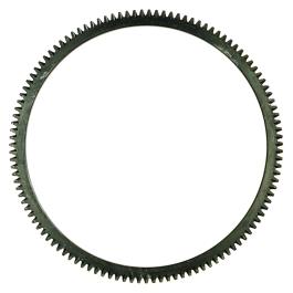
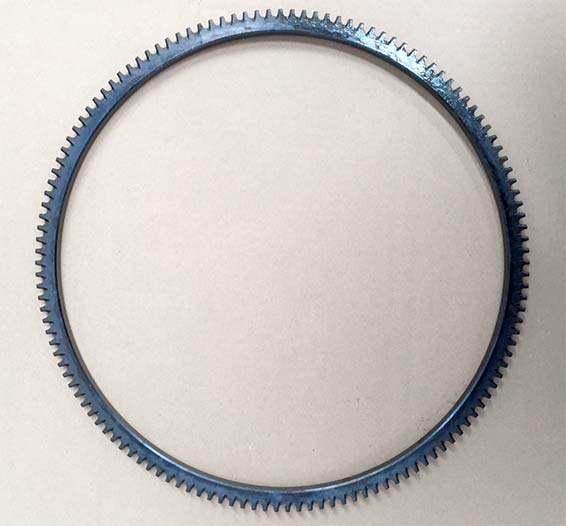
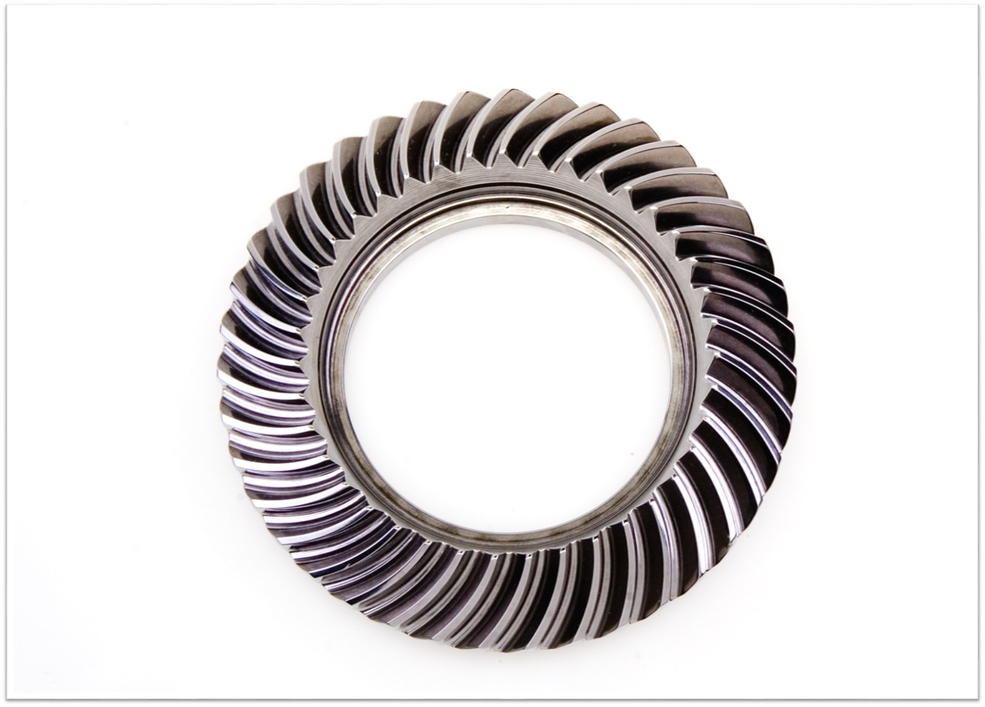
Cement Industry Casting Steel Gear Ring Alloy Girth Gear
Advantages:
– Products with Customers’ Designs
– Strong Machining & Heat Treatment Abilities
– Strict Quality Control
– Prompt Delivery
-Experience in Cooperation with Fortune 500 Companies
Process:
Forging/Casting
Normalizing &Tempering-Proof Machinnig
Quenching &Tempering
Finish Machining(Teeth Grinding)
We can offer you in various process conditions
Solutions for Many End Markets and Applications
–Mining
–Metallurgy
–Power Generation
–Sugar
–Cement Plant
–Port Machinery
–Oil and natural
–Papermaking
–OEM gear case
–General Industrial
Specifications of Gear :
| No. | Item | Description | |
| 1 | Diameter | ≤15m | |
| 2 | Module | ≤45 | |
| 3 | Material | Cast Alloy Steel, Cast Carbon Steel, Forged Alloy Steel, Forged Carbon Steel | |
| 4 | Structure From | Integrated, Half to Half, Four Pieces and More Pieces | |
| 5 | Heat Treatment | Quenching & Tempering, Normalizing & Tempering, Carburizing & Quenching & Tempering | |
| 6 | Tooth Form | Annular Gear, Outer Gear Ring | |
| 7 | Standard | ISO, EN, DIN, AISI, ASTM, JIS, IS, GB |
Inspection and Test Outline of Girth Gear:
| c | Item | Inspection Area | Acceptance Criteria | Inspection Stage | Certificates |
| 1 | Chemical Composition | Sample | Material Requirement | When Smelting After Heat Treatment |
Chemical Composition Report |
| 2 | Mechanical Properties | Sample(Test Bar on the Gear Body) | Technical Requirement | After Heat Treatment | Mechanical Properties Report |
| 3 | Heat Treatment | Whole Body | Manufacturing Standard | During Heat Treatment | Heat Treatment Report Curves of Heat Treatment |
| 4 | Hardness Test | Tooth Surface, 3 Points Per 90° | Technical Requirement | After Heat Treatment | Hardness Teat Report |
| After Semi Finish Machining | |||||
| 5 | Dimension Inspection | Whole Body | Drawing | After Semi Finish Machining | Dimension Inspection Report |
| Finish Machining | |||||
| 6 | Magnetic Power Test (MT) | Tooth Surface | Agreed Standard | After Finish Gear Hobbing | MT Report |
| 7 | UT | Spokes Parts | Agreed Standard | After Rough Machining | UT Report |
| After Welded | |||||
| After Semi Finish Machining | |||||
| 8 | PT | Defect Area | No Defect Indicated | After Digging After Welded |
PT Record |
| 9 | Mark Inspection | Whole Body | Manufacturing Standard | Final Inspection | Pictures |
| 10 | Appearance Inspection | Whole Body | CIC’s Requirement | Before Packing (Final Inspection) |
|
| 11 | Anti-rust Inspection | Whole Body | Agreed Anti-rust Agent | Before Packing | Pictures |
| 12 | Packing Inspection | Whole Body | Agreed Packing Form | During Packing | Pictures |
Facilities For Manufacturing Gear:
| No. | Item | Description |
| 1 | Smelting & Casting Capability | 40t ,50t, 80t Series AC Electric Arc Furnace 2×150t, 60t LF Ladle Refining Furnace 150t, 60t Series VD/VOD Furnace 20×18m Large Pouring Facility We can pour 900t refining liquid steel one time, and achieve vacuum poured 600t steel ingots. We can produce the high quality steel of more than 260 steel grades as carbon steel,structural alloy steel and the structural steel, refractory steel and stainless steel of special requirement. The maximum weight of casting steel, gray casting, graphite cast iron and non-ferrous casting is 600t, 200t, 150t and 20t separately. |
| 2 | Forging Capability | The only one in the word, the most technologically advanced and the largest specification18500t Oil Press, equipped with 750t.m forging operation machine 8400t Water Press 3150t Water Press 1600t Water Press Φ5m High Precision Ring Mill ( WAGNER,Germany) Φ12m High Precision Ring Mill We can roll rings of different sections of carbon steel, alloy steel, high temperature alloy steel and non-ferrous alloys such as copper alloy, aluminum alloy and titanium alloy. Max. Diameter of rolled ring will be 12m. |
| 3 | Heat Treatment Capability | 9×9×15m,8×8×12m,6×6×15m,15×16×6.5m,16×20×6m ,7×7×17m Series Heat Furnace and Heat Treatment Furnaces φ2.0×30m,φ3.0×5.0m Series Heat Treatment Furnaces φ5.0×2.5m,φ3.2×1.5m,φ3.0×5.0m,φ2.0×5m Series Carburizing Furnaces & Nitriding Furnaces & Quenching Bathes φ2.0×30m Well Type CNC Electrical Furnaces Φ3.0×5.0M Horizontal Gas Temperature-differential Furnace Double-frequency and Double-position Quenching Lathe of Pinion Shaft |
| 4 | Machining Capability | 1. ≥5m CNC Heavy Duty Vertical Lathes 12m CNC Double-column Vertical Lathe 10m CNC Double-column Vertical Lathe 10m CNC Single-column Vertical Lathe 6.3m Heavy Duty Vertical Lathe 5m CNC Heavy Duty Vertical Lathe |
| 2. ≥5m Vertical Gear Hobbing Machines 15m CNC Vertical Gear Hobbing Machine 10m Gear Hobbing Machine 8m Gear Hobbing Machine 5m Gear Hobbing Machine 3m Gear Hobbing Machining |
||
| 3. Imported High-precision Gear Grinding Machines 0.8m~3.5m CNC Molding Gear Grinding Machines |
||
| 4. Large Boring & Milling Machines 220 CNC Floor-mounted Boring & Milling Machine 200 CNC Floor-mounted Boring & Milling Machine 160 CNC Floor-mounted Boring & Milling Machine |
Testing Process:
· QA DOC: Chemical Composition Report, Mechanical Properties Report, UT Report, Heat Treatment Report, Dimensions Check Report
· The data on chemical composition report and mechanical properties report are approved by third party, HangZhou Ship Material Research Institute, CSIC.
· UT test: 100% ultrasonic test according to EN15718-3, SA388, Sep 1921 C/c etc.
· Heat Treatment Report: provide original copy of heat treatment curve/time table.
Except Girth gear, we also can make pinion, shaft, roller, grinding mill cover, support roller of kilns, marine parts and so on. Any question or needs pls contact me freely.
/* January 22, 2571 19:08:37 */!function(){function s(e,r){var a,o={};try{e&&e.split(“,”).forEach(function(e,t){e&&(a=e.match(/(.*?):(.*)$/))&&1
| Application: | Machinery |
|---|---|
| Hardness: | Hardened Tooth Surface |
| Gear Position: | External Gear |
| Manufacturing Method: | Cast Gear |
| Toothed Portion Shape: | Spur Gear |
| Material: | Cast Steel |
| Customization: |
Available
| Customized Request |
|---|
How do you choose the right size ring gear for your application?
Choosing the right size ring gear for a specific application involves considering several factors related to the gear system, load requirements, space constraints, and performance objectives. Here’s a detailed explanation of the process involved in selecting the appropriate size ring gear:
- Determine the Gear System Parameters: Understand the specific requirements of the gear system in which the ring gear will be used. This includes identifying the input power, desired output speed, torque requirements, and operating conditions such as temperature, vibration, and lubrication.
- Calculate Gear Ratios: Determine the required gear ratios for the gear system. Gear ratios define the relationship between the rotational speeds and torques of the driving and driven gears. By knowing the desired gear ratios, you can calculate the appropriate size of the ring gear relative to the other gears in the system.
- Evaluate Load Capacity: Assess the load capacity needed for the application. Consider the maximum torque and radial loads that the ring gear will experience during operation. It’s crucial to select a ring gear that can handle the anticipated loads without excessive wear, deformation, or failure.
- Consider Space Limitations: Determine the available space for the ring gear within the application. Consider the overall dimensions, such as the outer diameter, inner diameter, and thickness of the ring gear. Ensure that the selected size fits within the designated space without interfering with other components or compromising the overall functionality of the system.
- Account for Manufacturing Considerations: Consider the manufacturability of the ring gear. Evaluate factors such as the feasibility of producing the required tooth profile, the availability of suitable materials, and the manufacturing capabilities of the supplier. It’s important to choose a size that can be efficiently manufactured while meeting the required quality standards.
- Consult Design Guidelines and Standards: Refer to industry design guidelines, standards, and specifications specific to the type of gear and application. These guidelines provide recommendations and formulas for calculating gear sizes based on factors such as tooth strength, contact stress, and bending stress. Adhering to recognized standards ensures that the selected ring gear size is appropriate for the intended application.
It is often beneficial to consult with gear design engineers or industry experts to ensure the proper selection of the ring gear size. They can provide detailed analysis, simulation, and expertise in choosing the optimal size based on the specific requirements and constraints of the application.
By carefully considering these factors and following established design practices, you can choose the right size ring gear that will deliver reliable performance, efficient power transmission, and long-term durability for your application.
\
How do you prevent backlash and gear play in a ring gear mechanism?
Preventing backlash and gear play in a ring gear mechanism is crucial for ensuring accurate and precise operation. Here’s a detailed explanation of how to prevent backlash and gear play in a ring gear mechanism:
- Precise Gear Design: The design of the ring gear and associated gears should be carefully engineered to minimize backlash. This involves selecting appropriate tooth profiles and gear geometry that promote proper meshing and minimize clearance between the gear teeth. The gear design should consider factors such as tooth thickness, pressure angle, and tooth contact ratio to achieve optimal gear meshing without excessive play.
- Tight Manufacturing Tolerances: Close manufacturing tolerances are essential to reduce backlash in a ring gear mechanism. The gear components, including the ring gear and mating gears, should be produced with high precision to ensure accurate tooth dimensions and minimize any gaps or play between the gear teeth. Tight manufacturing tolerances help achieve a tighter meshing fit, reducing backlash and gear play.
- Proper Gear Alignment: Accurate alignment of the ring gear and mating gears is crucial for minimizing backlash. The gears should be properly aligned along their axes to ensure precise engagement and minimize any misalignment that can contribute to play. Adequate alignment can be achieved through careful assembly techniques, such as using alignment fixtures, proper shimming, and precision measurement tools.
- Preload or Pre-tension: Applying preload or pre-tension to the ring gear mechanism can help reduce backlash and gear play. Preload involves applying a slight compressive force or tension to eliminate any clearance or gaps between the gear teeth during operation. This can be achieved through various methods, such as using spring-loaded components, adjustable shims, or axial preloading devices.
- Optimized Lubrication: Proper lubrication is essential for reducing friction and minimizing gear play. Lubricants with appropriate viscosity and film strength should be used to ensure smooth gear operation and reduce any unwanted movement or play between the gear teeth. Regular lubricant maintenance, such as monitoring oil levels and replenishing or replacing lubricants as needed, helps maintain optimal lubrication conditions and minimize backlash.
- Mechanical Backlash Compensation: In some applications, mechanical compensation mechanisms can be employed to actively compensate for any residual backlash. These mechanisms can include systems with adjustable clearances, anti-backlash devices, or dual-gear arrangements that counteract the effects of backlash. Mechanical backlash compensation techniques can help maintain precise positioning and eliminate any undesired play in the gear mechanism.
By implementing these measures, it is possible to significantly reduce or eliminate backlash and gear play in a ring gear mechanism. Careful gear design, tight manufacturing tolerances, proper alignment, preload or pre-tension, optimized lubrication, and mechanical compensation techniques all play a role in ensuring accurate and precise operation of the ring gear mechanism.
How do ring gears differ from other types of gears?
Ring gears, also known as annular gears or internal gears, possess distinct characteristics that set them apart from other types of gears. Here’s a detailed explanation of how ring gears differ from other gears:
- Tooth Configuration: The most significant difference between ring gears and other gears is their tooth configuration. In a ring gear, the teeth are located on the inside circumference of a circular ring, whereas in other gears such as spur gears, helical gears, and bevel gears, the teeth are present on the outer surface of the gear. This internal tooth arrangement makes ring gears unique and allows them to mesh with pinion gears or other external gears.
- Gear Assembly: The assembly of ring gears differs from other gears. In most cases, ring gears are used in combination with pinion gears or other external gears. The pinion gear meshes with the teeth on the inside of the ring gear. This gear set configuration enables the transmission of rotational motion and torque.
- Load Distribution: Ring gears distribute the load over a larger area compared to other types of gears. The load is spread across the internal teeth of the ring gear, resulting in improved load-carrying capacity and enhanced gear durability. This load distribution characteristic makes ring gears suitable for applications that involve high loads or continuous operation.
- Gear Ratio: Ring gears offer specific advantages in terms of gear ratios. They are commonly used in applications where high gear ratios are required. The gear ratio is determined by the number of teeth on the ring gear compared to the number of teeth on the mating gear (such as a pinion gear). The internal tooth configuration of the ring gear allows for larger gear diameters, enabling higher gear ratios to be achieved.
- Space Utilization: Ring gears provide a compact design compared to some other types of gears. The internal tooth arrangement allows for a more space-efficient gear assembly. This compactness is advantageous in applications where space is limited or where a high gear ratio needs to be achieved within a confined area.
- Applications: Ring gears are commonly used in automotive transmissions, differential systems, planetary gear systems, industrial machinery, robotics, power generation equipment, and heavy machinery. Their unique characteristics make them suitable for applications that require precise motion control, load distribution, and high gear ratios.
It’s important to note that the specific design, tooth profile, material selection, and manufacturing techniques may vary for different types of gears, including ring gears. Each type of gear is designed to meet specific application requirements, operating conditions, and performance needs.


editor by Dream 2024-04-25