Product Description
Pinion Rack Round Worm Screw Helical Hypoid Straight Ring Spiral Forged Bevel Spur Differential Steering Internal Box Spline Plastic Nylon Stainless Steel Gear
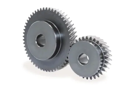
Gears:
The processing production line we see can produce the following gears: spur gears, helical gears, bevel gears, spiral bevel gears, straight bevel gears, internal gears, worm gears, gear rack
| Process | CNC machining,CNC milling, cnc lathe machining |
| Available Material | 1.Stainless Steel: SS201, SS303, SS304, SS316, SS416, SS420,etc. |
| 2.Steel: C45, 40Cr, 42CrMo, 20CrNiMo, 20CrMnTi, etc. (AISI 1045, 5140, 4140/4142, 8620 etc.) | |
| 3. Brass:C36000 ( C26800), C37700 ( HPb59), C38500( HPb58), C27200CuZn37), C28000(CuZn40),etc. | |
| 4.Bronze: C51000, C52100, C54400, etc. | |
| 5. Iron: 1213, 12L14,1215,etc. | |
| 6. Aluminum: Al6061, Al6063,Al2571,Al7075 etc | |
| 7. Carbon steel:AISI1006,AISI1571,AISI1571,etc. | |
| 8.Nylon PA66,MC901,POM plastic ects | |
| Hardness | HRC50~55 |
| Quality Control | ISO9001 and ISO14001 |
| Dimension bore tolerances | -/+0.01mm |
| Quality standard | AGMA, JIS, DIN |
| Size/Color | Gears and parts dimensions are according to drawings from customer, and colors are customized |
| Surface treatment | black oxide,Zn-plated,ni-plated,tin-plated,chrome plated,passivated,sandblast and anodize,chromate,polish,electro painting,black anodize,plain,H.D.G,etc. |
| Dimensions Tolerance | ±0.01mm or more precise |
| Samples confirmation and approval | samples shipped for confirmation and shipping cost paid by customers |
| Package | Inner clear plastic bag/outside carton/wooden pallets/ or any other special package as per customer’s requirements. |
We also have injection molding machines, which can produce plastic nylon gears according to your needs
Related products
Transmission products:
Gearbox/gear reducer:
Click here for more details!
Customization process
Support Customized Gears from Customers’ drawings and samples and Various non-standard customization
1.Products Discussions
Customers send drawings oramples, and quote according to customers’ requirements.
2.Molds designing
Designing 3D drawings and optimizing the products.
3.Drawing confirmation
Sending the mold drawing tothe customers , and the customers CHINAMFG for confirmation.
4.Molds Construction
Manufacture molds accurately and accurately according to the drawings.
5.Moulds Inspection and Moulds Test
Detect various indicators of molds and optimization of inner cavities.
6.Sample Aprroval from Customer
Customers approve the samples and confirm them for bulk production.
7.Mass Production
Bulk production according to customers’s PO
8.PO Finished
Shipping to the customer andthe customers receive the gears.
If you need other customized requirements, please click here to contact us!
Why Choose Us
We enthusiastically provide sincere and prompt service to our customers and establish sustainable business relationship with them.
100% Factory inspection, we are responsible for any problems subjected to malfunction in warranty period.
We Can Provide You:
- On-time Delivery with More Choice
- Product Solutions and Service
- Long Quality Guarantee
- Local Technical Support
- Fast Response to Customers’ Feedbacks in 24 hours
Also I would like to take this opportunity to give a brief introduction of our CHINAMFG company:
Our company is a famous manufacturer of agriculture gearbox,worm reduce gearbox, PTO shafts, Sprockets ,rollar chains, bevel gear, pulleys and racks in china.
We have exported many products to our customers all over the world, we have long-time experience and strong technology support.
You also can check our website to know for more details, if you need our products catalogue, please contact with us.
Company information
| Application: | Motor, Electric Cars, Motorcycle, Machinery, Marine, Toy, Agricultural Machinery, Car |
|---|---|
| Hardness: | Hardened Tooth Surface |
| Gear Position: | External Gear |
| Manufacturing Method: | Cast Gear |
| Toothed Portion Shape: | Bevel Wheel |
| Material: | Cast Iron |
| Samples: |
US$ 999/Piece
1 Piece(Min.Order) | |
|---|
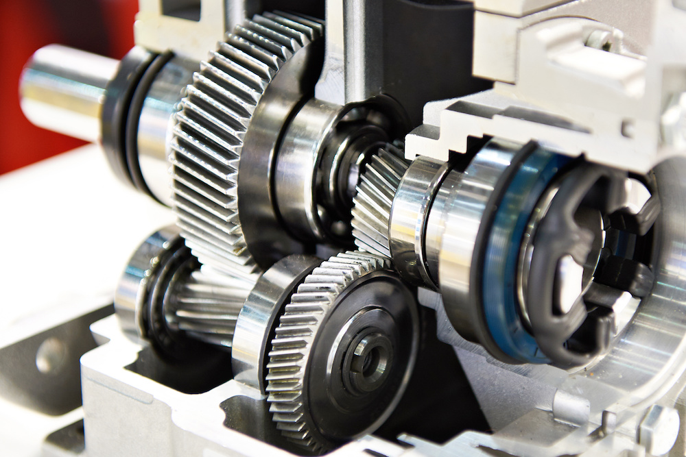
Can you provide examples of machinery that use helical gears?
Helical gears are widely used in various types of machinery and mechanical systems. Their unique tooth geometry and smooth operation make them suitable for applications that require high torque transmission, precision, and low noise levels. Here are some examples of machinery and equipment that commonly utilize helical gears:
- Industrial Gearboxes: Helical gears are extensively employed in industrial gearboxes used in various industries such as manufacturing, mining, oil and gas, and power generation. These gearboxes are responsible for transmitting power and adjusting rotational speed in large machinery and equipment, including conveyors, mixers, crushers, extruders, and heavy-duty pumps.
- Automotive Transmissions: Helical gears play a crucial role in automotive transmissions, both manual and automatic. They facilitate the smooth shifting of gears and the transfer of power from the engine to the wheels. Helical gears are commonly found in the main transmission system, differential gears, and gear sets used in the gearbox.
- Machine Tools: Many types of machine tools, such as milling machines, lathes, and grinding machines, rely on helical gears for precise motion control and power transmission. Helical gears are used in the spindle drives, feed mechanisms, and gearboxes of these machines, enabling accurate and efficient metal shaping, cutting, and finishing operations.
- Rotary Compressors: Helical gears are employed in rotary compressors, which are widely used in industries such as refrigeration, HVAC, and pneumatic systems. The helical gears in these compressors help to compress and transfer gases or fluids, generating the desired pressure and flow rates.
- Printing Presses: High-speed printing presses utilize helical gears in their drive systems. The gears enable the precise synchronization of various components, such as rollers, cylinders, and plate cylinders, ensuring accurate paper feeding, ink distribution, and image transfer during the printing process.
- Paper and Pulp Industry: Helical gears are utilized in machinery used in the paper and pulp industry, including paper mills and paperboard manufacturing plants. They are employed in equipment such as pulpers, refiners, stock pumps, and paper machine drives, facilitating the processing, refining, and transportation of pulp and paper materials.
- Construction Equipment: Helical gears are found in various construction machinery, such as cranes, excavators, loaders, and bulldozers. They are used in the drivetrains, swing mechanisms, and hydraulic systems of these machines, providing the necessary torque, speed control, and power transmission capabilities.
- Marine Propulsion Systems: Helical gears are utilized in marine propulsion systems, including marine engines, outboard motors, and ship propulsion systems. They enable efficient power transmission from the engine to the propeller, ensuring smooth and reliable operation of watercraft.
- Wind Turbines: In wind energy applications, helical gears are commonly used in wind turbine gearboxes. They help convert the low-speed rotation of the turbine blades into higher rotational speeds required by the electrical generators, enabling efficient energy generation from wind power.
- Food Processing Machinery: Helical gears find applications in the food processing industry, where they are used in equipment such as mixers, conveyors, extruders, and packaging machines. They facilitate the movement of ingredients, blending, and precise control of processing parameters.
These examples demonstrate the versatility and widespread use of helical gears across various industries and applications. The unique characteristics of helical gears make them suitable for a wide range of machinery that requires smooth, efficient, and reliable power transmission.

How do you ensure proper alignment when connecting helical gears?
Proper alignment is crucial when connecting helical gears to ensure smooth and efficient operation, minimize noise and vibration, and prevent premature wear. Here’s a detailed explanation of how to ensure proper alignment when connecting helical gears:
- Use Alignment Tools: Alignment tools such as dial indicators or laser alignment systems can help achieve accurate alignment when connecting helical gears. These tools measure the relative positions of the gears and aid in adjusting their positions to achieve proper alignment. By using precise alignment tools, engineers can ensure the gears are correctly positioned for optimal meshing and load distribution.
- Check Gear Meshing: Proper gear meshing is essential for alignment. Ensure that the teeth of the helical gears are correctly meshed, and there is sufficient contact across the entire tooth width. Improper meshing, such as excessive or insufficient contact, can lead to noise, vibration, and accelerated wear. Adjust the gear positions if necessary to achieve optimal meshing conditions.
- Verify Center Distance: The center distance between the two helical gears must be accurately determined and maintained. The center distance affects the gear meshing and tooth contact pattern. Measure and verify the center distance using appropriate measuring tools, such as calipers or micrometers, to ensure it aligns with the gear design specifications. Make adjustments if needed to achieve the correct center distance.
- Check Axial Alignment: Proper axial alignment is crucial for helical gears. The axial alignment refers to the alignment of the gear shafts and the gears along the axial direction. Misalignment can cause uneven load distribution, increased noise and vibration, and accelerated wear. Use appropriate alignment tools to check and adjust the axial alignment, ensuring the gears are aligned along the same axis.
- Consider Preload and Backlash: Preload and backlash are important considerations for helical gears. Preload refers to applying a slight axial force to the gears to ensure proper contact and minimize backlash. Backlash is the small amount of clearance between the gear teeth. Follow the gear manufacturer’s recommendations for preload and backlash values and make adjustments as necessary during the gear connection process.
- Check Parallelism: The gear shafts should be parallel to each other to ensure proper alignment. Use precision measuring tools, such as straightedges or feeler gauges, to verify the parallelism of the gear shafts. If any deviation is detected, adjust the gear positions or make appropriate modifications to achieve parallel alignment.
- Consider Thermal Expansion: Take into account the potential thermal expansion of the gear components. Gears can expand or contract due to temperature variations during operation. Ensure proper clearances and allowances are considered to accommodate thermal expansion without compromising alignment. Consult the gear manufacturer’s guidelines or industry standards for recommended clearances based on the expected operating temperature range.
- Follow Manufacturer’s Guidelines: Always refer to the gear manufacturer’s guidelines, specifications, and recommendations for proper alignment procedures. Different gear types and designs may have specific alignment requirements. Manufacturers often provide detailed instructions and alignment tolerances that should be followed to achieve optimal gear performance and longevity.
By following these alignment practices, engineers can ensure the proper alignment of helical gears, promoting smooth and efficient gear operation, reducing noise and vibration, and maximizing gear system lifespan.
What are the benefits of using a helical gear mechanism?
A helical gear mechanism offers several benefits that make it a preferred choice in many applications. Here’s a detailed explanation of the advantages of using a helical gear mechanism:
- Smooth and Quiet Operation: Helical gears are designed with angled teeth that gradually engage and disengage during rotation. This gradual engagement reduces noise and vibration, resulting in smoother and quieter operation compared to other gear types such as spur gears. The continuous contact between the teeth also helps in distributing the load more evenly, reducing the risk of concentrated wear or damage.
- High Load-Carrying Capacity: The inclined teeth of helical gears allow for greater tooth engagement compared to spur gears. This increased tooth contact area results in improved load distribution and higher load-carrying capacity. Helical gears can transmit higher torque and handle heavier loads, making them suitable for applications that require high power transmission and torque transfer.
- Efficient Power Transmission: The inclined tooth profile of helical gears enables smooth and efficient power transmission. The gradual engagement of teeth minimizes shock loads and ensures a continuous transfer of power without sudden jolts or interruptions. This efficiency is particularly beneficial in applications where precise motion control, energy efficiency, and smooth acceleration are required.
- Versatility and Adaptability: Helical gears can be manufactured in various configurations to suit different application requirements. They can be designed as parallel helical gears for transmitting power between parallel shafts, double helical gears (herringbone gears) for balancing axial thrust, crossed helical gears (screw gears) for non-parallel and non-intersecting shafts, and other specialized variations. This versatility allows for a wide range of gear arrangements and applications.
- Improved Tooth Strength: The helical tooth profile provides better tooth strength compared to spur gears. The inclined teeth distribute the load over a larger contact area, reducing stress concentrations and enhancing the gear’s resistance to wear, pitting, and tooth breakage. This improved tooth strength contributes to the overall durability and longevity of the gear mechanism.
- Compact Design: Helical gears can achieve a high gear ratio in a relatively compact design. The inclined teeth allow for more teeth to be in contact at any given time, enabling a higher gear ratio within a limited space. This compactness is advantageous when there are size constraints or when a smaller gear mechanism is desired without sacrificing performance.
- High Efficiency: Due to their smooth operation and improved tooth engagement, helical gears offer high mechanical efficiency. They minimize power losses caused by friction, heat generation, and vibration, resulting in efficient power transmission. The high efficiency of helical gears is particularly beneficial in applications where energy conservation and reduced operating costs are important considerations.
In summary, the benefits of using a helical gear mechanism include smooth and quiet operation, high load-carrying capacity, efficient power transmission, versatility, improved tooth strength, compact design, and high mechanical efficiency. These advantages make helical gears suitable for a wide range of applications, including automotive transmissions, industrial machinery, power generation equipment, robotics, and more.


editor by CX 2023-09-22