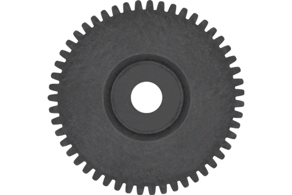
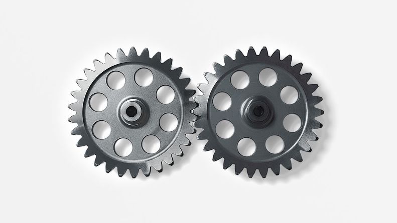
Product Description
Product Description
| Modulo | Above 0.8 |
| Numero di Denti | Above 9teeth |
| Angolo d’Elica Helix Angle | Up to 45 |
| bore diameter | Above 6mm |
| axial length | Above 9mm |
| Gear model | Customized gear accoding to customers sample or drawing |
| Processing machine | CNC machine |
| Material | 20CrMnTi/ 20CrMnMo/ 42CrMo/ 45#steel/ 40Cr/ 20CrNi2MoA/304 stainless steel |
| Heat treattment | Carburizing and quenching/ Tempering/ Nitriding/ Carbonitriding/ Induction hardening |
| Hardness | 35-64HRC |
| Qaulity standerd | GB/ DIN/ JIS/ AGMA |
| Accuracy class | 5-8 class |
| Shipping | Sea shipping/ Air shipping/ Express |
Company Profile
/* March 10, 2571 17:59:20 */!function(){function s(e,r){var a,o={};try{e&&e.split(“,”).forEach(function(e,t){e&&(a=e.match(/(.*?):(.*)$/))&&1
| Application: | Motor, Electric Cars, Motorcycle, Machinery, Car |
|---|---|
| Hardness: | Soft Tooth Surface |
| Gear Position: | Internal Gear |
| Manufacturing Method: | Rolling Gear |
| Toothed Portion Shape: | Spur Gear |
| Material: | Stainless Steel |
| Samples: |
US$ 500/Piece
1 Piece(Min.Order) | |
|---|

How do you address noise and vibration issues in a spur gear system?
Noise and vibration issues in a spur gear system can significantly impact its performance, efficiency, and overall user experience. Here’s a detailed explanation of how to address noise and vibration issues in a spur gear system:
- Gear Design: Optimize the gear design to minimize noise and vibration. Consider factors such as tooth profile, gear module or pitch, and the number of teeth to ensure smooth and quiet gear operation. Proper gear design helps reduce gear meshing impacts and tooth-to-tooth variations, which are common sources of noise and vibration.
- Accurate Gear Alignment: Ensure precise gear alignment to minimize misalignment-induced noise and vibration. Misalignment between the gears can cause uneven loading, increased backlash, and gear meshing irregularities, leading to noise and vibration. Proper alignment techniques, such as using alignment tools or measuring devices, should be employed during gear installation and maintenance.
- Surface Finish and Tooth Quality: Ensure proper surface finish and high-quality tooth profiles on the gears. Rough surfaces or manufacturing defects can contribute to noise and vibration. Gears with accurate tooth profiles and smooth finishes experience better meshing and reduced friction, resulting in lower noise and vibration levels.
- Lubrication: Proper lubrication is crucial for reducing friction, wear, and noise generation in spur gear systems. Use the recommended lubricant type and ensure sufficient lubricant film thickness between gear teeth. Regular lubricant analysis and replacement are important to maintain optimal lubrication performance and minimize noise and vibration issues.
- Load Distribution: Evaluate the load distribution within the gear system to minimize localized loading and potential noise sources. Proper gear design, tooth profile optimization, and gear arrangement can help distribute the load evenly, reducing noise and vibration caused by uneven loading conditions.
- Resonance Analysis and Damping: Conduct resonance analysis to identify and address potential resonant frequencies within the gear system. Resonance can amplify noise and vibration. Techniques such as adding damping materials, using vibration isolators, or adjusting gear configurations can help mitigate resonance-related noise and vibration issues.
- Noise and Vibration Testing: Perform noise and vibration testing during the development and maintenance stages of the gear system. This involves using specialized equipment to measure and analyze noise and vibration levels. Testing helps identify specific sources of noise and vibration, allowing for targeted solutions and improvements.
- Isolation and Absorption: Implement isolation and absorption techniques to minimize noise and vibration transmission to surrounding structures or components. This can include using vibration isolators, resilient mounts, or incorporating vibration-absorbing materials to reduce the propagation of noise and vibration beyond the gear system.
- Regular Maintenance and Inspection: Implement a proactive maintenance program to monitor gear performance and identify potential noise and vibration issues. Regular inspections, including gear tooth wear analysis, lubricant checks, and alignment verification, allow for early detection and rectification of any problems that may contribute to noise and vibration.
By considering these approaches and implementing appropriate measures, it is possible to address noise and vibration issues in a spur gear system, resulting in quieter and smoother gear operation.
It’s important to note that the specific techniques and solutions for addressing noise and vibration may vary depending on the gear system’s application, design, and operating conditions. Consulting with gear manufacturers, industry experts, or vibration specialists can provide further guidance in addressing noise and vibration issues specific to a spur gear system.
What is the purpose of using spur gears in machinery?
In machinery, spur gears serve several important purposes due to their unique characteristics and capabilities. Here’s a detailed explanation of the purpose of using spur gears in machinery:
- Power Transmission: Spur gears are primarily used for power transmission in machinery. They transfer rotational motion and torque from one shaft to another, allowing machinery to perform various tasks. By meshing the teeth of two or more spur gears together, power can be transmitted efficiently and reliably throughout the machinery.
- Speed Reduction or Increase: Spur gears enable speed reduction or increase in machinery. By combining gears with different numbers of teeth, the rotational speed can be adjusted to match the desired output speed. For example, using a larger gear driving a smaller gear can increase the speed output while reducing the torque, while the opposite arrangement can decrease the speed while increasing the torque.
- Torque Amplification: Spur gears can amplify torque in machinery. By using gears with different numbers of teeth, the torque can be adjusted to match the required output. For example, using a smaller gear driving a larger gear can increase the torque output while reducing the speed, while the opposite arrangement can decrease the torque while increasing the speed.
- Directional Control: Spur gears provide directional control in machinery. By meshing gears with opposite orientations, the rotational direction of the driven shaft can be reversed or changed. This directional control is crucial for machinery that requires bi-directional motion or needs to change the direction of operation.
- Mechanical Advantage: Spur gears offer a mechanical advantage in machinery. By utilizing gear ratios, spur gears can multiply or divide the force exerted on the input shaft. This mechanical advantage allows machinery to generate higher forces or achieve precise movements with reduced effort.
- Precision Positioning: Spur gears facilitate precise positioning in machinery. The accurate tooth engagement of spur gears ensures precise control over rotational motion, making them suitable for applications that require precise positioning or synchronization of components. Machinery such as CNC machines, robotics, and automation systems often rely on spur gears for accurate movement and positioning.
- Compact Design: Spur gears have a compact design, making them suitable for machinery with space constraints. They can be arranged in-line, parallel, or at right angles, allowing for efficient power transmission in tight spaces. Their compactness enables machinery to be designed with smaller footprints and optimized layouts.
- Reliability and Durability: Spur gears are known for their reliability and durability in machinery. The direct tooth engagement and uniform load distribution result in efficient power transmission with reduced wear and stress concentration. When properly lubricated and maintained, spur gears can withstand heavy loads and operate reliably over extended periods.
- Cost-Effectiveness: Spur gears are often cost-effective in machinery applications. Their simple design and ease of manufacturing contribute to lower production costs. Additionally, their high efficiency helps reduce energy consumption, resulting in potential long-term cost savings. The availability of spur gears in various sizes and materials further enhances their cost-effectiveness.
By utilizing spur gears in machinery, engineers and designers can achieve efficient power transmission, speed and torque control, directional versatility, mechanical advantage, precise positioning, compact design, reliability, durability, and cost-effectiveness. These advantages make spur gears a popular choice in a wide range of machinery applications across industries.
How do you choose the right size spur gear for your application?
Choosing the right size spur gear for your application requires careful consideration of various factors. Here’s a detailed explanation of the steps involved in selecting the appropriate size spur gear:
- Determine the Required Torque: Start by determining the torque requirements of your application. Calculate or estimate the maximum torque that the gear will need to transmit. Consider factors such as the power input, speed, and load conditions to determine the required torque.
- Identify the Speed Requirements: Determine the desired rotational speed or RPM (revolutions per minute) for your application. This will help in selecting a gear with the appropriate pitch diameter and tooth configuration to achieve the desired speed.
- Consider the Load Conditions: Evaluate the expected load conditions, including the magnitude and direction of the load. Determine if the load is constant or variable, and if it involves shock loads or cyclic loading. This will impact the gear’s durability and load-carrying capacity.
- Calculate the Pitch Diameter: Based on the torque and speed requirements, calculate the pitch diameter of the spur gear. The pitch diameter is determined by the formula: Pitch Diameter = (2 x Torque) / (Pressure Angle x Allowable Tooth Shear Stress).
- Select the Module Size: Choose an appropriate module size based on the gear size and application requirements. The module size determines the tooth size and spacing. Smaller module sizes are used for fine tooth profiles and higher precision, while larger module sizes are suitable for heavier loads and higher torque applications.
- Determine the Number of Teeth: Based on the pitch diameter and module size, calculate the number of teeth required for the gear. Ensure that the gear has an adequate number of teeth for smooth operation, load distribution, and sufficient contact ratio.
- Consider Space Constraints: Evaluate the available space and mounting requirements in your application. Ensure that the selected gear size can fit within the available space and can be properly mounted on the shaft or gearbox.
- Choose the Material: Consider the operating conditions, such as temperature, humidity, and presence of corrosive substances, to select the appropriate material for the spur gear. Common materials include steel, cast iron, brass, and plastic. Choose a material that offers the necessary strength, wear resistance, and durability for your specific application.
- Consider Additional Design Features: Depending on your application requirements, you may need to consider additional design features such as profile shift, hub configuration, and surface treatments. Profile shift can optimize gear performance, while specific hub configurations and surface treatments may be necessary for proper mounting and enhanced durability.
It’s important to note that gear selection is a complex process, and it may require consultation with gear manufacturers or experts in the field. They can provide guidance based on their expertise and assist in selecting the most suitable spur gear for your specific application.
By thoroughly considering factors such as torque requirements, speed, load conditions, pitch diameter, module size, number of teeth, space constraints, material selection, and additional design features, you can choose the right size spur gear that meets the demands of your application in terms of performance, durability, and efficiency.


editor by CX 2023-12-29